Carbon-brush seat

A technology of carbon brush seat and carbon brush, which is applied in the direction of current collectors, electrical components, rotating current collectors, etc., and can solve problems such as uneven wear parts, unfavorable smooth movement of carbon brushes, and wear

Active Publication Date: 2013-10-23
TAIWAN LONG HAWN ENTERPRISES
View PDF6 Cites 1 Cited by
  • Summary
  • Abstract
  • Description
  • Claims
  • Application Information

AI Technical Summary

Problems solved by technology

[0005] 2. The leg 5a of the torsion spring 5 swings with the fixed pin 6 as the fulcrum, that is, when it pushes the carbon brush 3 in a biased manner, one side of the carbon brush 3 will be close to the inner wall of the container 2a, and This interference situation will not be conducive to the smooth movement of the carbon brush 3, and the influence of the bias force on the carbon brush 3 will cause uneven wear parts
[0006] 3. The elongated groove 2b on the support frame 2 is set to facilitate the displacement of the wire 4, and the wire 4 can still maintain a good electrical connection effect when the carbon brush 3 moves due to wear, so its length must be greater than The straight-line distance between the fixed points at both ends is made, but in this way, it is easy to cause the exposed part of the wire 4 and the edge of the elongated groove 2b to be worn due to direct contact

Method used


Image

  • Carbon-brush seat
  • Carbon-brush seat
  • Carbon-brush seat

Examples


Embodiment Construction

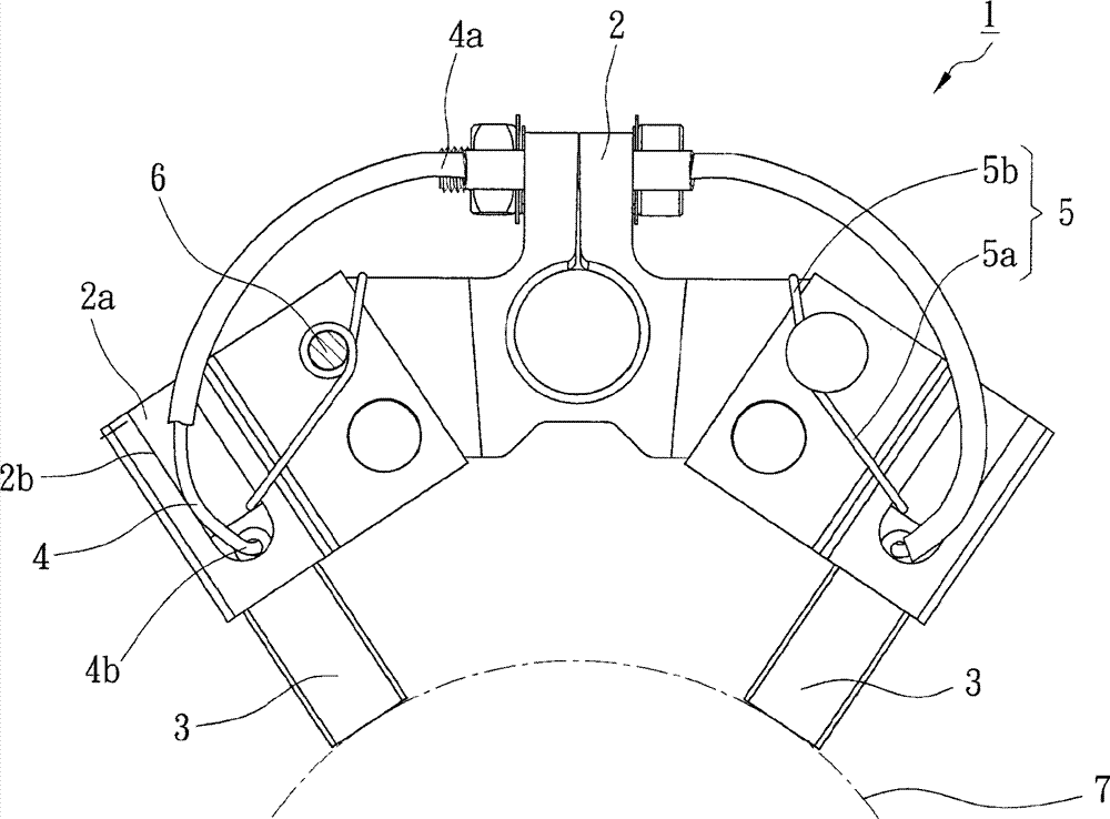
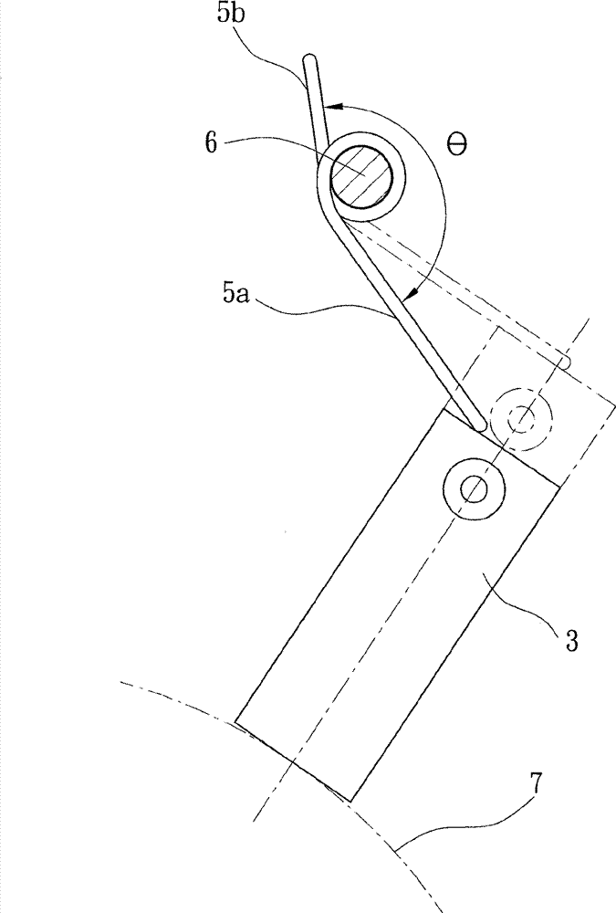
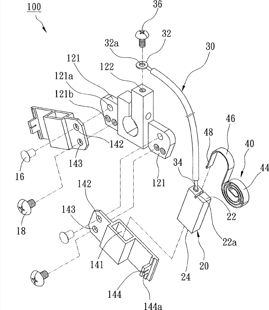
[0046] The carbon brush holder provided by the present invention includes a support frame, a carbon brush and a coil spring. Wherein, at least one side of the support frame has a carbon brush accommodating groove penetrating through the top and bottom surfaces; the carbon brush is movably arranged in the carbon brush accommodating groove, and has a top end and a bottom end; the coil spring has a curved portion and An extension portion, wherein the curled portion has a crimping center fixed on the support frame, the crimping center is located on one side of the carbon brush accommodating groove, and is located in the range of the parallel extension direction of the top surface and the bottom surface; The extension portion has a pressing end spanning the top surface, and the pressing end abuts against the top end of the carbon brush.

[0047] In one embodiment, the support frame has a protrusion adjacent to the carbon brush receiving groove, and the curled portion of the coil sprin...


PUM


Abstract

Disclosed is a carbon-brush seat including a support frame, two carbon brushes and two coil springs, wherein two ends of the support frame are each provided with a carbon-brush accommodating groove and the carbon brushes are movably accommodated in the accommodating grooves. The coil springs are provided with coil central positions which are arranged in a range of parallel extension directions of top faces and bottom faces of the carbon-brush accommodating grooves. The coil springs apply acting forces which are parallel to moving directions of the carbon brushes to the carbon brushes so that in a moving process, both of the carbon brushes can bear stable and uniform jacking forces. Therefore, an effect that the carbon brushes are in excellent contact with a surface of a collecting ring is ensured.

Description

Technical field [0001] The present invention relates to a slip ring device, and more specifically refers to a carbon brush holder that can improve the effect of electrical conduction. Background technique [0002] figure 1 Shown is a known carbon brush holder 1, which is composed of a supporting frame 2, two carbon brushes 3, two wires 4, and two torsion springs 5. Wherein, each side of the support frame 2 has a pocket 2a, and each pocket 2a has a long cross-sectional groove 2b; the two carbon brushes 3 are respectively placed in each pocket 2a; the two wires 4 are covered with insulation One end 4a of the wire 4 is fixed to the top of the support frame 2, and the other end 4b is fixed to the upper half of the carbon brush 3; the two torsion springs 5 ​​are respectively wound on a fixing pin 6 provided on the support frame 2. And its pushing force promotes the carbon brush 3 to move downward, thereby ensuring that the bottom end of the carbon brush 3 can maintain contact with th...

Claims


Application Information

Patent Timeline
Patent Type & Authority Applications(China)
IPC IPC(8): H01R39/415
Inventor 游孟萩廖树城
Owner TAIWAN LONG HAWN ENTERPRISES
Why Eureka
Try Eureka