
Fan motor driver, method for generating pulse width modulation signal and control circuit

A fan motor and control circuit technology, applied in the direction of DC motor speed/torque control, control system, excitation or armature current control, etc., can solve problems such as high material, and achieve the effect of reducing external resistance and material cost

Active Publication Date: 2016-05-04
RICHTEK TECH
View PDF7 Cites 0 Cited by
  • Summary
  • Abstract
  • Description
  • Claims
  • Application Information

AI Technical Summary

Problems solved by technology

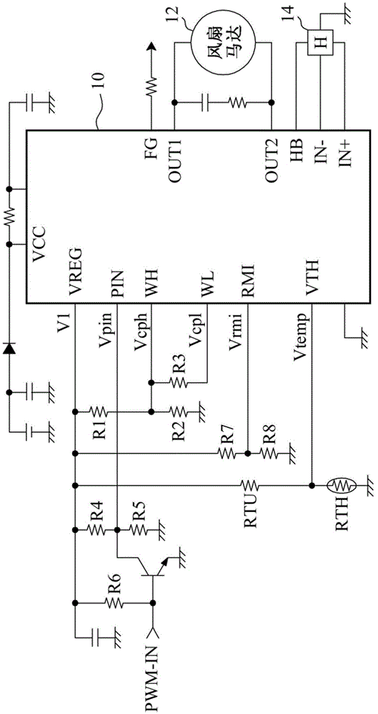
[0004] However, if figure 1 As shown, in order to accurately control the switching ratio of the PWM signals OUT1 and OUT2 from the outside of the fan motor driver 10, multiple precise external resistors R1~R8, RTU, and RTH are required to set the voltages Vcph, Vcpl, Vrmi, and Vtemp And Vpin, so there will be a higher material (BillOfMaterials; BOM) cost

Method used


Image

  • Fan motor driver, method for generating pulse width modulation signal and control circuit
  • Fan motor driver, method for generating pulse width modulation signal and control circuit
  • Fan motor driver, method for generating pulse width modulation signal and control circuit

Examples


Embodiment Construction

[0056] In order to make the object, technical solution and advantages of the present invention clearer, the embodiments of the present invention will be further described in detail below in conjunction with the accompanying drawings. Here, the exemplary embodiments and descriptions of the present invention are used to explain the present invention, but not to limit the present invention.

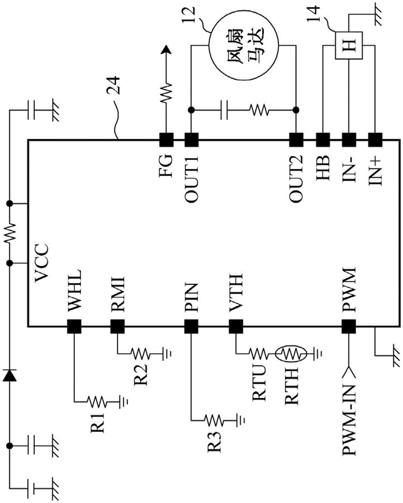
[0057] image 3According to the fan motor driver 24 of the present invention and the fan motor control circuit based on it, the resistors R1, R2, and R3 are respectively connected between the pins WHL, RMI, PIN and the ground of the fan motor driver 24, and the resistors The RTU and the thermistor RTH are connected in series between the pin VTH of the fan motor driver 30 and the ground terminal. The fan motor driver 24 is based on the resistance value of the resistors R1, R2 and R3 and the total resistance value of the resistors RTU and RTH instead of connecting to the ground. The voltages ...


PUM


Abstract

The embodiment of the invention discloses a fan motor driver used for providing a pulse-width modulation signal in order to decide the rotating speed of a fan. The fan motor driver controls the duty ratio the pulse-width modulation signal according to the resistance value of a multiple external resistors connected with the pins of the fan motor driver, rather than the voltage on the multiple pins. As a result, a fan motor control circuit established on the basis of the fan motor driver is capable of reducing the number of external resistors and material cost. The embodiment of the invention also discloses a fan motor control circuit.

Description

technical field [0001] The invention relates to a fan motor control circuit, in particular to a core device of the fan motor control circuit. Background technique [0002] The fan motor driver is the core device for establishing the fan motor control circuit. In the application of the fan motor, it is often necessary to adjust the fan speed from the outside in order to achieve the optimization of the air volume and noise. For this reason, the fan motor control circuit usually connects resistors in series outside the fan motor driver to adjust the speed of the fan motor driver. The fan motor driver compares the voltage level for control with the internally generated triangular wave to generate a pulse width modulation (PulseWidthModulation; PWM) signal, and controls the fan speed by its on-off ratio (duty). For example figure 1 Shown is a single-phase full-wave (single-phase full-wave) fan motor control circuit based on the existing fan motor driver 10. The fan motor driver...

Claims


Application Information

Patent Timeline
Patent Type & Authority Patents(China)
IPC IPC(8): H02P7/00H02P7/29
Inventor 汪若瑜陈安东
Owner RICHTEK TECH
Learn More