Improved system of expanding optical module digital diagnostic monitoring

A technology of digital diagnosis and optical module, applied in the direction of transmission monitoring/testing/fault measurement system, etc., can solve problems such as DDM detection error not up to standard, affecting production efficiency and product instability

Active Publication Date: 2013-10-23
SHENZHEN GIGALIGHT TECH
View PDF5 Cites 8 Cited by
  • Summary
  • Abstract
  • Description
  • Claims
  • Application Information

AI Technical Summary

Problems solved by technology

[0009] Because of the above reasons, there will always be a certain proportion of products in the production process whose DDM detection error does not meet the standard, and usually need to replace the microcontroller or sampling resistor, thus affecting production efficiency and increasing product instability

Method used


Image

  • Improved system of expanding optical module digital diagnostic monitoring
  • Improved system of expanding optical module digital diagnostic monitoring
  • Improved system of expanding optical module digital diagnostic monitoring

Examples


Embodiment Construction

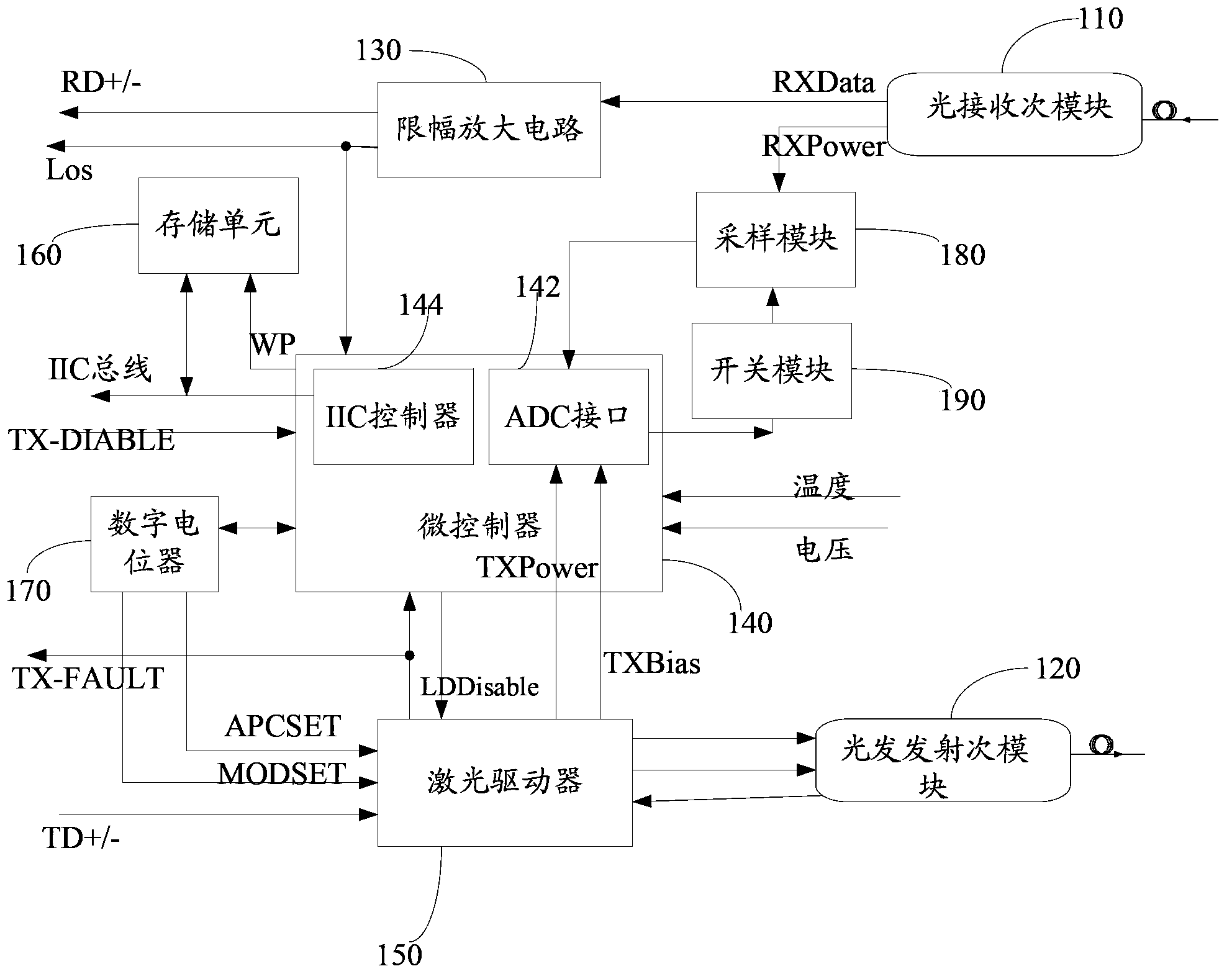
[0028] Such as figure 1 Shown is the block diagram of the improved system for digital diagnosis and monitoring of extended optical modules.

[0029] An improved system for digital diagnosis and monitoring of extended optical modules, comprising: an optical receiving sub-module 110, an optical transmitting sub-module 120, a limiting amplifier 130, a laser driver 150 for providing driving current to the optical transmitting sub-module, and a microcontroller 140, a digital potentiometer 170, and a storage unit 160; it also includes a sampling module 180 and a switch module 190.

[0030] The light receiving sub-module 110 is connected to the limiting amplifier 130 and the microcontroller 140 respectively, the storage unit 160 is connected to the microcontroller 140, and the digital potentiometer 170 is connected to the laser driver respectively. 150 is connected to the microcontroller 140 , and the laser driver 150 is also connected to the light emitting sub-module 120 .

[0031...


PUM


Abstract

The invention discloses an improved system of expanding optical module digital diagnostic monitoring. The improved system comprises an optical receiving submodule, an optical emission submodule, a limiting amplifier, a laser driver, a micro controller, a digital potentiometer, a storage unit, a sampling module and a switch module, wherein the laser driver is used for providing driving current for the optical emission submodule; the switch module comprises a field-effect transistor; the sampling module comprises a first sampling resistor and a second sampling resistor; the micro controller is also used for detecting input voltage; when the input voltage reaches a set threshold value, the switch module is controlled to be on; the sampling module outputs the composite resistance value of the first sampling resistor and the second sampling resistor; at the moment, the monitoring range of expanding optical module digital diagnosis is a first power range; when the input voltage is lower than the set threshold valve, the switch module is controlled to be off; the sampling module outputs the resistance value of the first sampling resistor; and at the moment, the monitoring range of expanding optical module digital diagnosis is a second power range. Therefore, the original monitoring range can be expanded, and the monitoring precision is improved.

Description

technical field [0001] The invention relates to an optical module improvement technology, in particular to a system for improving and expanding the digital diagnosis and monitoring range and precision of an optical module. Background technique [0002] There are two types of optical modules: those with DDM (digital diagnostic monitoring) function and those without DDM function. Those with DDM function are called intelligent optical modules. Using the intelligent optical module, the network management unit can monitor the temperature, power supply voltage, laser bias current and transmit and receive optical power of the transceiver module in real time. The measurement of these parameters can help the network management unit find out the location of the fault in the optical fiber link, simplify the maintenance work, and improve the reliability of the system. [0003] Commonly used DDM solutions are divided into hardware and microcontrollers. The hardware solution is simple to...

Claims


Application Information

Patent Timeline
Patent Type & Authority Applications(China)
IPC IPC(8): H04B10/07
Inventor 秦伟东
Owner SHENZHEN GIGALIGHT TECH
Why Eureka
Try Eureka