Disposable dental interproximal slice saw

A one-time, adjacent surface technology, applied in the direction of dental saws, etc., can solve the problems of inconvenient operation, irregular slice cutting, unsafe and other problems, and achieve the effect of convenient operation.

Inactive Publication Date: 2016-05-25
JILIN AGRICULTURAL UNIV
View PDF10 Cites 0 Cited by
  • Summary
  • Abstract
  • Description
  • Claims
  • Application Information

AI Technical Summary

Problems solved by technology

[0002] At present, in the orthodontic treatment, the treatment methods involving the cutting of the proximal surface of the teeth mainly include mechanical power sand cutting and manual proximal grinding strip cutting; the former is used in the oral cavity, which is extremely unsafe , and the slice cutting is not standardized, it is easy to produce excessive partial slice cutting of the tooth and change the normal shape of the tooth; the latter is inconvenient and limited in the operation in the mouth, and it is easy to cause pollution or infection, damage the soft tissue, and cause discomfort to the patient

Method used


Image

  • Disposable dental interproximal slice saw
  • Disposable dental interproximal slice saw
  • Disposable dental interproximal slice saw

Examples


Embodiment 1

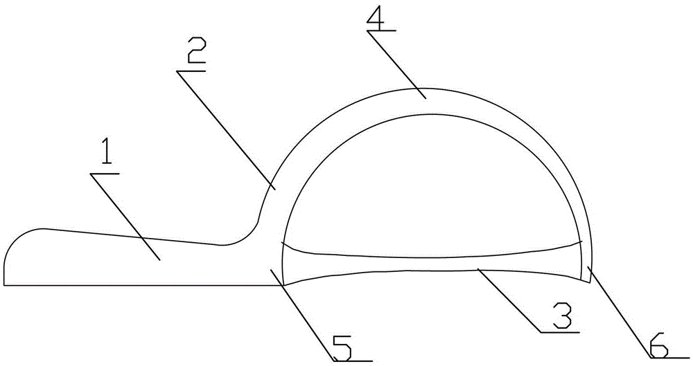
[0022] figure 1 It is the first embodiment of the present invention. Such as figure 1 As shown, the saw handle 1 is fixedly connected to the left end 5 of the saw frame 2, the saw handle 1 and the arc saw bow 2 are on the same plane, and the left end 5 of the saw frame is wider than the right end of the saw frame 3 width. The width of the left end 5 of the saw frame is 5 mm, and the width of the right end 6 of the saw frame is 3.5 mm.

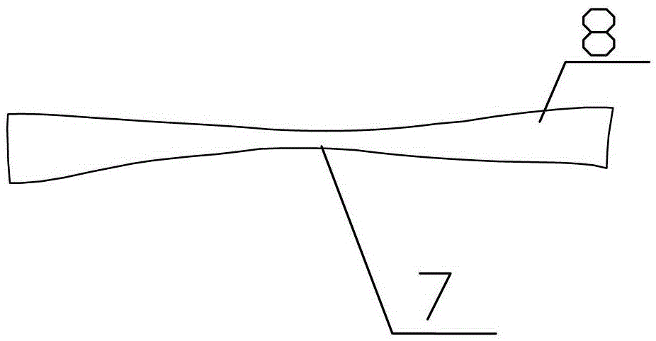
[0023] The adjacent sand bar 3 has a flat structure, and the adjacent sand bar 3 includes both ends 8 of the sand bar and a middle part 7 of the sand bar. The width of the two ends 8 of the sand bar is greater than the width of the middle part 7 of the sand bar. The width of the middle part 7 of the sand bar is 2 mm, and the width of both ends 8 of the sand bar is 5 mm. The saw handle 1 and the curved saw frame 2 are made of plastic. The adjacent sand bar 3 is fixed on the left end 5 of the saw frame and the right end 6 of the saw frame by...

Embodiment 2

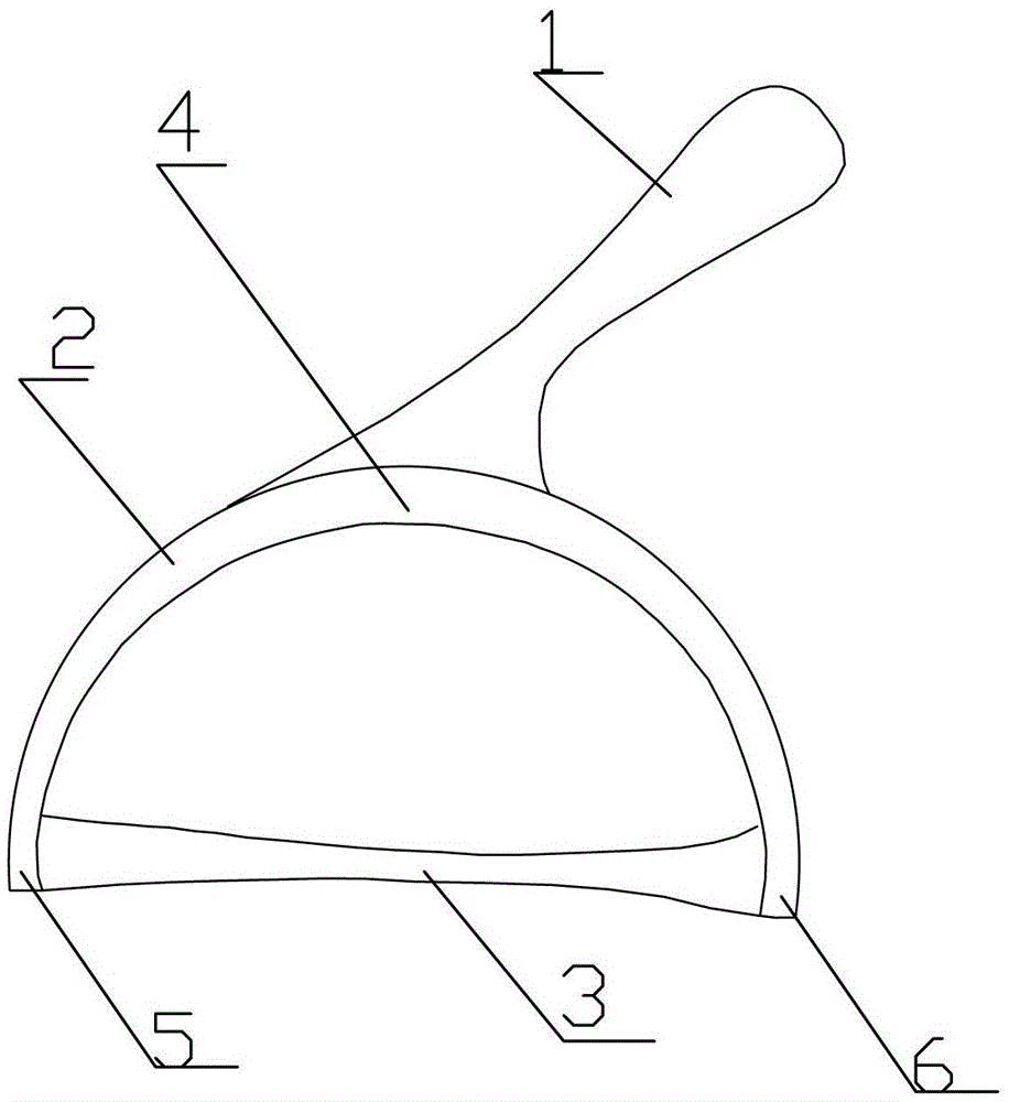
[0026] figure 2 It is the second embodiment of the present invention. Such as figure 2 As shown, the saw handle 1 is fixedly connected to the bow 4 of the arc saw frame 2, the saw handle 1 is perpendicular to the plane where the arc saw frame 2 is located, and the width of the left end 5 of the saw frame is the same as the width of the right end 6 of the saw frame , the width of the saw bow 4 is greater than the width of the left end 5 of the saw frame. The width of the saw bow 4 is 5 mm, the width of the left end 5 of the saw frame and the width of the right end 6 of the saw frame are both 3.5 mm.

[0027] The adjacent sand bar 3 has a flat structure, and the adjacent sand bar 3 includes both ends 8 of the sand bar and a middle part 7 of the sand bar. The width of the two ends 8 of the sand bar is greater than the width of the middle part 7 of the sand bar. The width of the middle part 7 of the sand bar is 2 mm, and the width of both ends 8 of the sand bar is 5 mm. The ...


PUM


Abstract

The invention relates to a disposable tooth adjacent face sheet cutting saw. The adjacent face sheet cutting saw comprises a saw handle, an arc-shaped saw rack and an adjacent face sand bar, wherein the saw handle is fixedly connected to the arc-shaped saw rack; the arc-shaped saw rack is of a flat structure and comprises a saw rack left end, a saw bow and a saw rack right end; both ends of the adjacent face sand bar are connected with the saw rack left and the saw rack right end of the arc-shaped saw rack respectively and fixedly. According to the disposable tooth adjacent face sheet cutting saw with the technical scheme, the arc-shaped saw rack can be used for buffering resistance during cutting of the adjacent face sand bar; as the diameter of the middle part of the adjacent face sand bar is smaller than that of both ends of the adjacent face sand bar, the adjacent face sand bar can enter a gap between adjacent teeth conveniently; a sand face of which both ends are wide and large is beneficial to expansion of tooth gaps and adjustment of tooth form; two types of sheet cutting saws are matched with different sand bars so as to be suitable for sheet cutting of various teeth at different parts, the operation is facilitated greatly and is safe and accurate.

Description

technical field [0001] The invention relates to the technical field of oral medical instruments, in particular to a disposable tooth-adjacent surface cutting saw. Background technique [0002] At present, in the orthodontic treatment, the treatment methods involving the cutting of the proximal surface of the teeth mainly include mechanical power sand cutting and manual proximal grinding strip cutting; the former is used in the oral cavity, which is extremely unsafe , and the sectioning is not standardized, it is easy to produce excessive partial sectioning of the teeth and change the normal shape of the teeth; the latter is inconvenient and limited in the operation of the mouth, and it is easy to cause pollution or infection, damage soft tissues, and cause discomfort to the patient. Contents of the invention [0003] The purpose of the present invention is to provide a disposable tooth-adjacent surface cutting saw, which changes the way the patient operates in the natural ...

Claims


Application Information

Patent Timeline
Patent Type & Authority Patents(China)
IPC IPC(8): A61C3/12
Inventor 刘玉芹吴东辉王桂敏庄金良尚颖刘泽
Owner JILIN AGRICULTURAL UNIV
Why Eureka
Try Eureka