

Inclined slider mechanism
A technology of inclined sliding block and limit mechanism, applied in metal processing equipment, perforating tools, manufacturing tools, etc., can solve the problems of reduced work efficiency, large punching force of punches, increased processing costs, etc., and achieves extended service life, Low punching force, improved strength and height
- Summary
- Abstract
- Description
- Claims
- Application Information
AI Technical Summary
Problems solved by technology
Method used
Image

Examples
Embodiment Construction
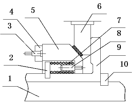
[0011] As an embodiment of the present invention, such as figure 1 As shown, a kind of oblique slider mechanism, comprises upper mold base, lower mold base 1 and punch 3, is fixedly connected with wedge base 9 on the lower mold base, and described wedge base 9 is L-shaped, and wedge base 9 An oblique slider 5 is arranged on it, a chute is provided on the oblique wedge seat 9, the oblique slider 5 can slide along the chute, and a resetting mechanism and a limit mechanism are arranged in the oblique slider 5. In this embodiment, as a preferred , the bottom surface of the oblique slider 5 has a half-through groove, the opening of the half-through groove is located on the side of the oblique slider 5 away from the wedge 6, the half-through groove is provided with a reset screw 8 along the horizontal direction, and the reset screw 8 is sleeved with Back-moving spring 7, on the wedge seat 9 near the opening of the half-pass groove and the position corresponding to the reset screw 8 ...
PUM
 Abstract
Description
Claims
Application Information