Transition connection device for finance binding machine

A technology of transitional connection and connection device, applied in the direction of binding, etc., can solve the problems of cumbersome operation, single function, paper misalignment, etc.

Inactive Publication Date: 2013-10-30
ZHEJIANG ZHIYUAN OFFICE EQUIP MFG
View PDF1 Cites 0 Cited by
  • Summary
  • Abstract
  • Description
  • Claims
  • Application Information

AI Technical Summary

Problems solved by technology

[0002] At present, for the binding of papers, files, and albums, the riveting binding method is generally used, which includes steps such as punching, pipe cutting, and riveting. Existing bookbinding machines generally only have the functions of punching or riveting. Relatively simple, for example, the invention patent with the patent number ZL200920113774.X discloses a punching and binding machine, which places the two mechanisms of punching and pressure riveting side by side, and the two mechanisms share a workbench. The file is moved to the riveting place for riveting
However, such a binding machine will cause misalignment of the perforated paper in the process of document movement, which will cause trouble for the riveting and affect the effect of the riveting
Moreover, such an operation is very cumbersome, has many steps, takes a long time, and is inefficient. The overall volume of the binding machine is large, and the transportation and use are not convenient enough.

Method used


Image

  • Transition connection device for finance binding machine
  • Transition connection device for finance binding machine
  • Transition connection device for finance binding machine

Examples


Embodiment 1

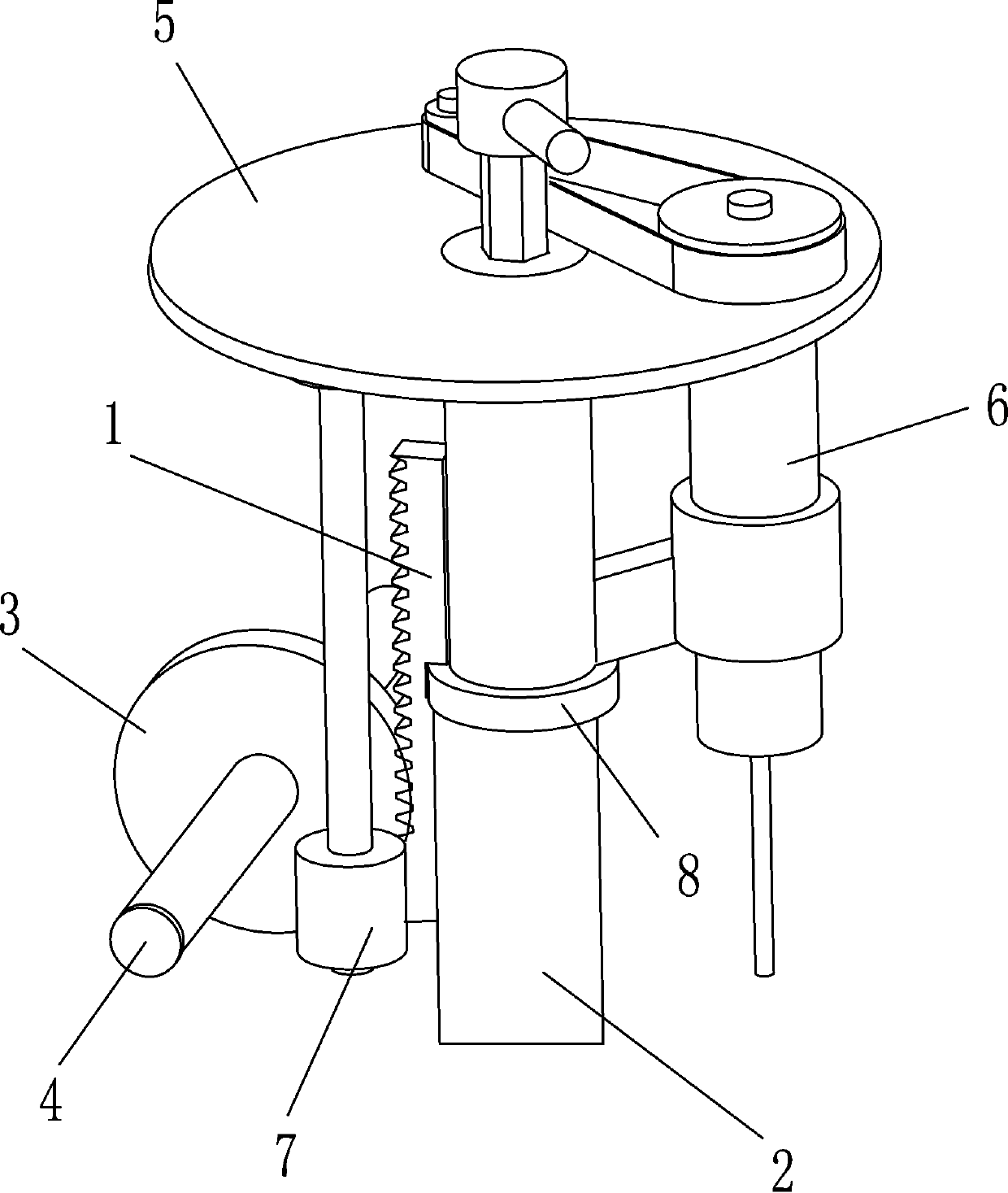
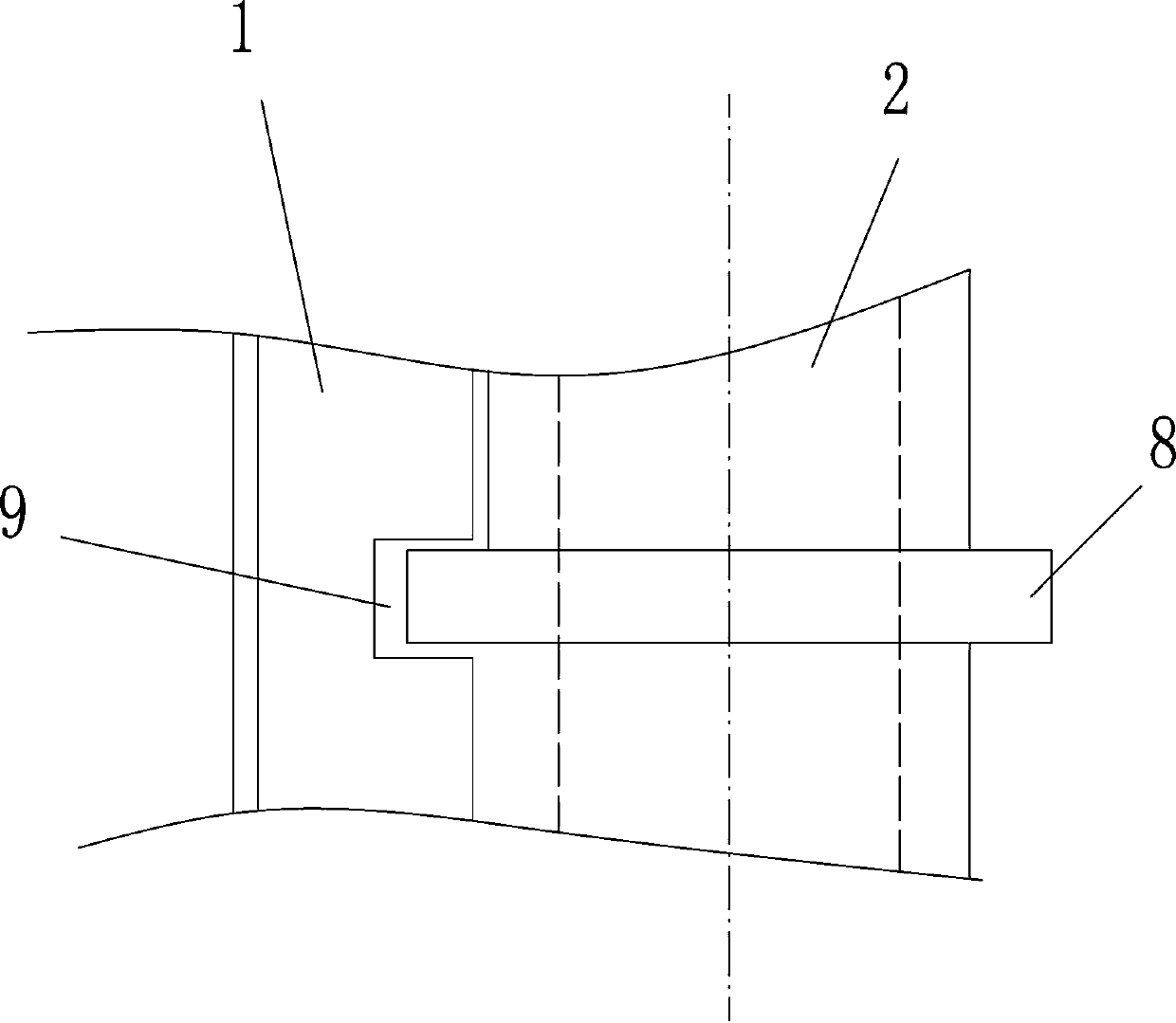
[0023] Embodiment 1, see attached figure 1 , 2 , a transition connection device for financial bookbinding machines, including a rack 1 and a rotating shaft 2, the rack 1 is connected to the rotating shaft 2 through a connecting device, the rack 1 and the gear 3 are meshed, and the gear 3 is fixed on the horizontal On the shaft 4, the horizontal shaft 4 drives the gear 3 to rotate to realize the lifting of the rack 1, and then the rack 1 is driven by the connecting device to lift the rotating shaft 2. The rotating shaft 2 is a hollow shaft, which is connected to the punching hole through the connecting part 5 The device 6 and the upper riveting device 7 are connected, and the position transformation of the punching device 6 and the upper riveting device 7 is realized through the rotation of the rotating shaft. The connecting part 5 is a circular plate in this embodiment, and of course a frame, Structures such as brackets; the connecting device includes a connecting ring 8 fixe...

Embodiment 2

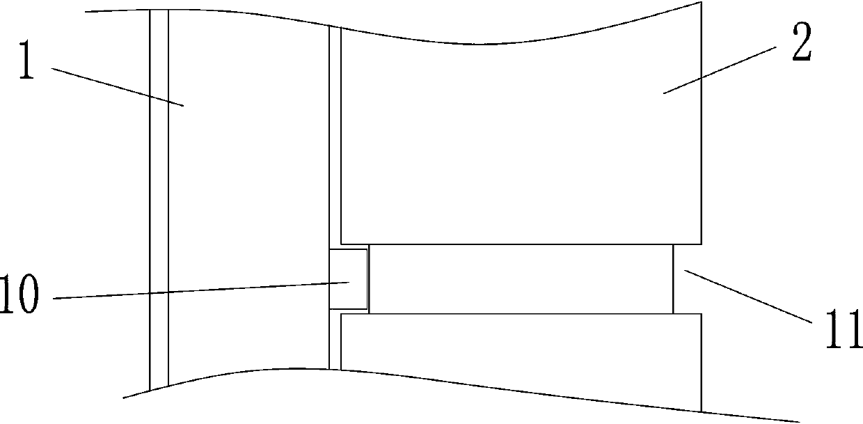
[0024] Embodiment 2, see attached image 3 , in this embodiment, the connecting device includes a clamping column 10 arranged on the rack 1, the rotating shaft 2 is provided with a ring groove 11 matching with the clamping column 10, and the ring groove 11 is along the The entire outer circumferential surface of the rotating shaft 2 extends. The rack 1 and the post can be integrally formed or assembled separately. The post 10 is inserted into the ring groove 11. The upper and lower surfaces of the post are flat and the ends are arc-shaped, which is convenient for matching with the ring groove. . All the other are with embodiment 1.

Embodiment 3

[0025] Embodiment 3, see attached Figure 4 , in this embodiment, the connecting device includes a rotating sleeve 12 rotatably installed on the rotating shaft 2, and the rack 1 is fixedly connected to the rotating sleeve 12. In this embodiment, the The rotating sleeve 12 is a bearing, the outer ring of the bearing is fixedly connected with the rack 1 , and the inner ring is fixedly connected with the rotating shaft. All the other are with embodiment 1.


PUM


Abstract

The invention discloses a transition connection device for a finance binding machine. The transition connection device for the finance binding machine comprises a spline and a rotation shaft. The spline is connected with the rotation shaft through a connection device, wherein the connection device comprises a connection ring fixed onto the rotation shaft. The spline is provided with an open groove which is matched with the connection ring, and the connection ring is fixedly connected with the rotation shaft in a welding or threaded mode. The transition connection device for the finance binding machine is simple in structure and low in price.

Description

technical field [0001] The invention relates to the technical field of office supplies, in particular to a transition connection device for a financial bookbinding machine. Background technique [0002] At present, for the binding of papers, files, and albums, the riveting binding method is generally used, which includes steps such as punching, pipe cutting, and riveting. Existing bookbinding machines generally only have the functions of punching or riveting. Relatively simple, for example, the invention patent with the patent number ZL200920113774.X discloses a punching and binding machine, which places the two mechanisms of punching and pressure riveting side by side, and the two mechanisms share a workbench. The file is moved to the riveting station for riveting. However, such a bookbinding machine will displace the perforated paper during the moving process of the document, which will cause trouble for the riveting and affect the effect of the riveting. And such operat...

Claims


Application Information

Patent Timeline
IPC IPC(8): B42B5/02B42B5/08
Inventor 王超棣阮永华
Owner ZHEJIANG ZHIYUAN OFFICE EQUIP MFG
Why Eureka
Try Eureka