
Passenger conveyors and steps for passenger conveyors

A technology of passenger conveying equipment and steps, applied in escalators, transportation and packaging, etc., can solve problems such as step differences, and achieve the effect of improving safety

Active Publication Date: 2015-08-12
HITACHI LTD
View PDF4 Cites 0 Cited by
  • Summary
  • Abstract
  • Description
  • Claims
  • Application Information

AI Technical Summary

Problems solved by technology

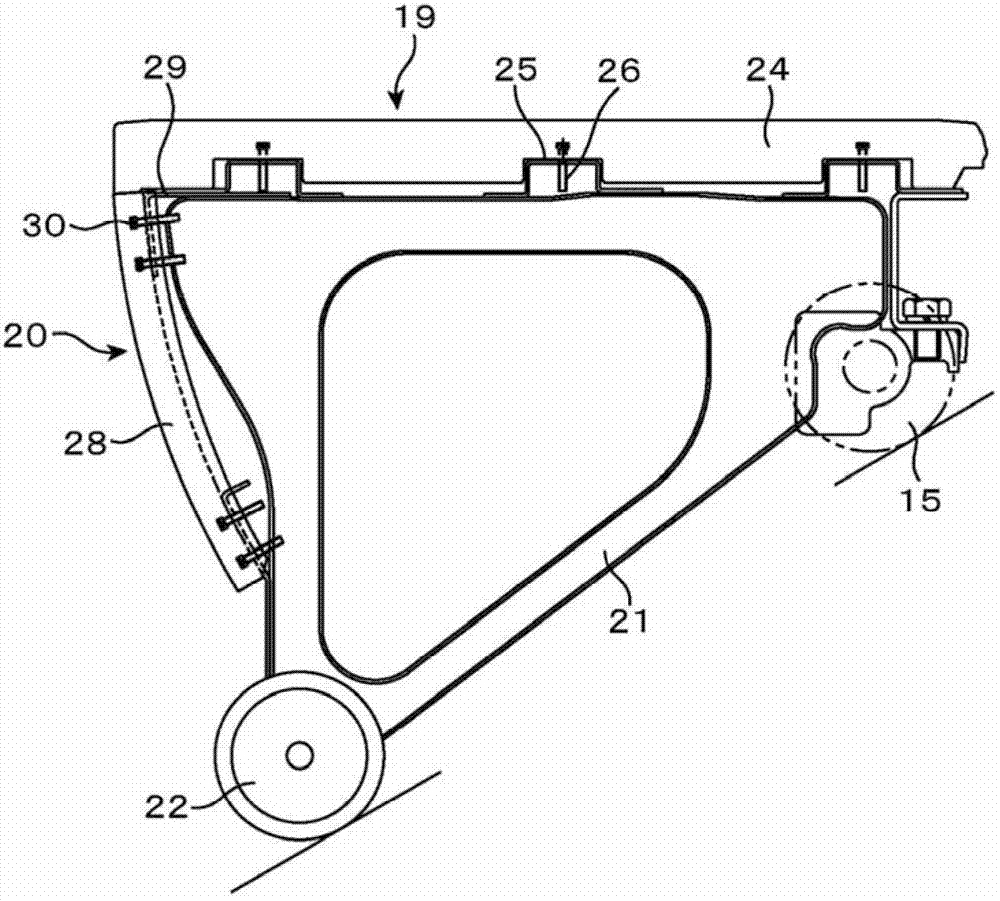
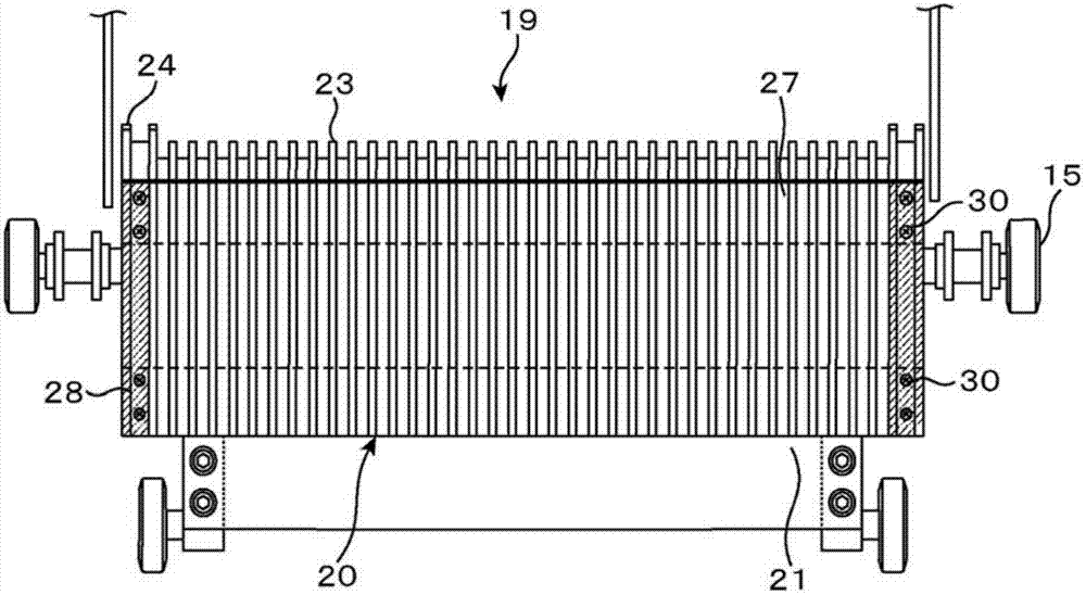
On the other hand, if Figure 9 As shown, when the anti-skid plate side end boundary member 24d is installed in front of a predetermined position along the step moving direction, or when the kick plate side end boundary member 28d is installed behind a predetermined position along the step moving direction, a step difference will occur. G

Method used


Image

  • Passenger conveyors and steps for passenger conveyors
  • Passenger conveyors and steps for passenger conveyors
  • Passenger conveyors and steps for passenger conveyors

Examples


Embodiment Construction

[0057] Embodiments of the present invention will be described below with reference to the drawings. In each drawing and each embodiment, the same or similar constituent elements are denoted by the same symbols, and repeated description thereof will be omitted.

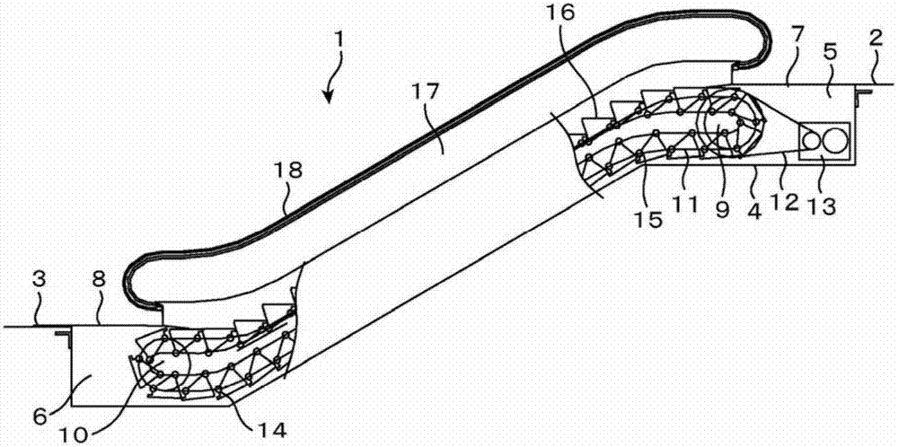
[0058] figure 1 It is a schematic diagram of the overall structure of the passenger conveying equipment. like figure 1 As shown, a passenger conveying device such as an escalator 1 has a frame body 4 arranged across an upper floor 2 and a lower floor 3 of a building structure, an upper machine room 5 and an upper machine room 5 arranged at both ends of the length direction of the frame body 4 The lower machine room 6, the upper doorway floor 7 covering the upper machine room 5 from above, the lower doorway floor 8 covering the lower machine room 6 from above, the upper terminal sprocket 9 installed in the upper machine room 5, and the lower The lower terminal sprocket 10 in the machine room 6, the left and right p...


PUM


Abstract

The invention provides a passenger delivery apparatus and steps of the passenger delivery apparatus, which enable the connection part of the side end boundary member of an anti-slip plate and the side end boundary member of a kickplate to be substantially smooth. Provided are the passenger delivery apparatus or the steps used therein. The passage delivery apparatus includes a frame body (4) spanning the upper floors and the lower floors of a building, and a plurality of steps (16) in circular connection in the frame body to perform circulated movement, each step is provided with a pedal (19) and a kickplate (20), the end of the pedal in the width direction is provided with the side end boundary member (24) of the anti-slip plate, each kickplate covers between the pedals of two adjacent steps to generate step difference, and the end of the pedal in the width direction is further provided with the side end boundary member (28) of the kickplate, and at least one connection part of the connection part of the side end boundary member of the anti-slip plate and the side end boundary member of the kickplate and the connection part of the side end boundary member of the kickplate and the side end boundary member of the anti-slip plate is subjected to chamfering or fillet machining.

Description

technical field [0001] The present invention relates to a passenger conveying device, in particular to a step of a passenger conveying device having a boundary member (Demarcation) to remind passengers to pay attention to. Background technique [0002] The steps of the passenger conveyor generally have steps on which passengers stand, risers covering the difference in steps formed between the steps of adjacent steps, and brackets for fixing the steps and the risers. [0003] The pedal has a cleat portion, a cleat side end boundary member, and a cleat base. The step movement direction is set at the end of the width direction of the anti-skid plate part, and is painted in yellow and other colors to remind passengers to pay attention. The anti-skid plate base is used to install the anti-skid plate part and the side end boundary member of the anti-skid plate. In addition, the cleat-side end boundary member is fixed to the cleat base by fixing screws. [0004] The kick plate ha...

Claims


Application Information

Patent Timeline
Patent Type & Authority Patents(China)
IPC IPC(8): B66B23/12
Inventor 松本达也宇津宫博文中村秀广
Owner HITACHI LTD
Learn More