Flow control valve

A technology of flow control valve and valve body, which is applied in the direction of fluid pressure actuators, servo motor components, mechanical equipment, etc. It can solve the problems of difficult passage and unstable flow control of hydraulic oil, and achieve the effect of stable flow control

Active Publication Date: 2013-10-30
刘资丰
View PDF4 Cites 5 Cited by
  • Summary
  • Abstract
  • Description
  • Claims
  • Application Information

AI Technical Summary

Problems solved by technology

[0004] However, when the hydraulic oil passes through the groove chamber 83 through the gap A between the aforementioned ring surface 912 and the opening 840, since the hydraulic oil itself has viscosity, that is to say, the viscosity of the hydraulic oil is higher when the temperature is lower, while the hydraulic oil When the temperature is higher, the viscosity is lower, so when the hydraulic oil flows through the annulus 912, since the annulus 912 is the entire peripheral surface with a predetermined surface area, the annulus 912 will have an effect on the flow of hydraulic oil. The resistance causes the "retention" phenomenon of the hydraulic oil. This "retention" phenomenon is more obvious when the viscosity of the hydraulic oil is high, making it difficult for the hydraulic oil to pass through the gap A, and the hydraulic oil is less viscous. It is easier to pass through the gap A, so the viscosity of the hydraulic oil due to different temperatures will cause different "retention" phenomena. The control of flow is unstable, which is the main problem that the present invention intends to improve

Method used


Image

  • Flow control valve
  • Flow control valve
  • Flow control valve

Examples


Embodiment Construction

[0028] The following examples are only used to illustrate the possible implementation aspects of the present invention, but they are not intended to limit the scope of protection of the present invention, and are described first.

[0029] See Figure 1 to Figure 6 The figure shown in the figure is the selected embodiment structure of the present invention, which is for illustrative purposes only, and is not limited by this structure in the patent application.

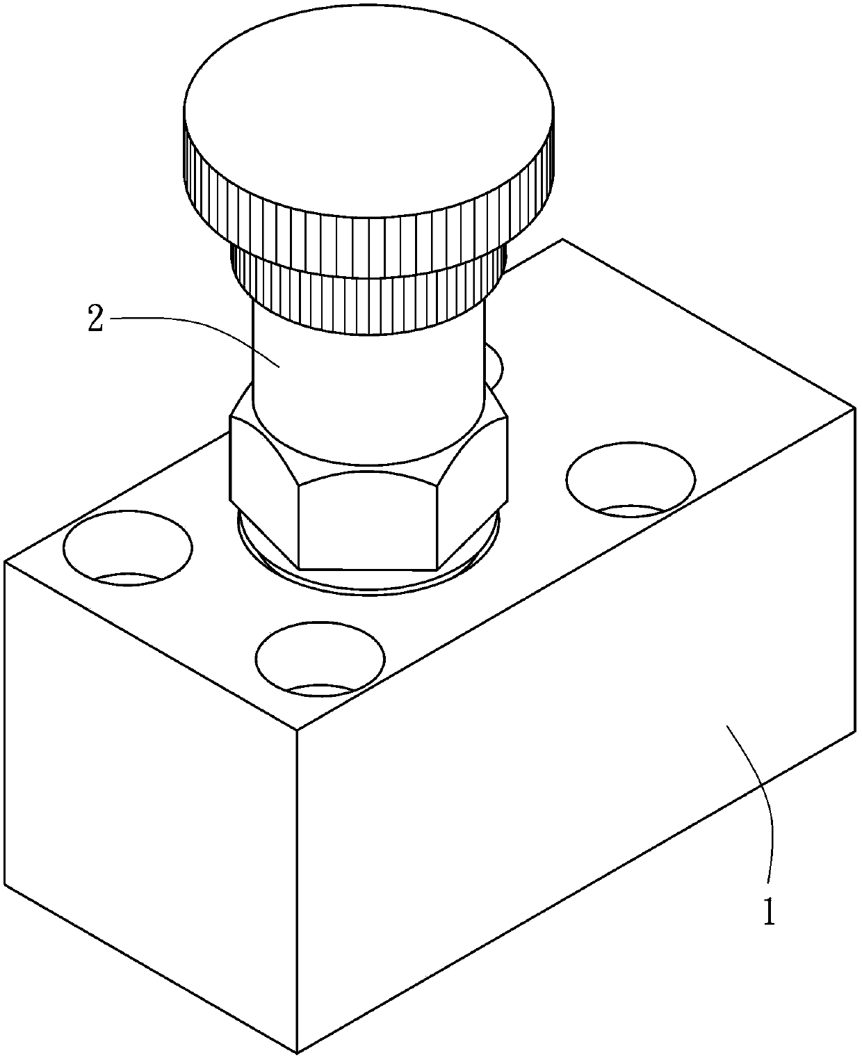
[0030] This embodiment provides a flow control valve, which is as Figure 1 to Figure 2 As shown, it includes a valve body 1 and an adjusting member 2, wherein:

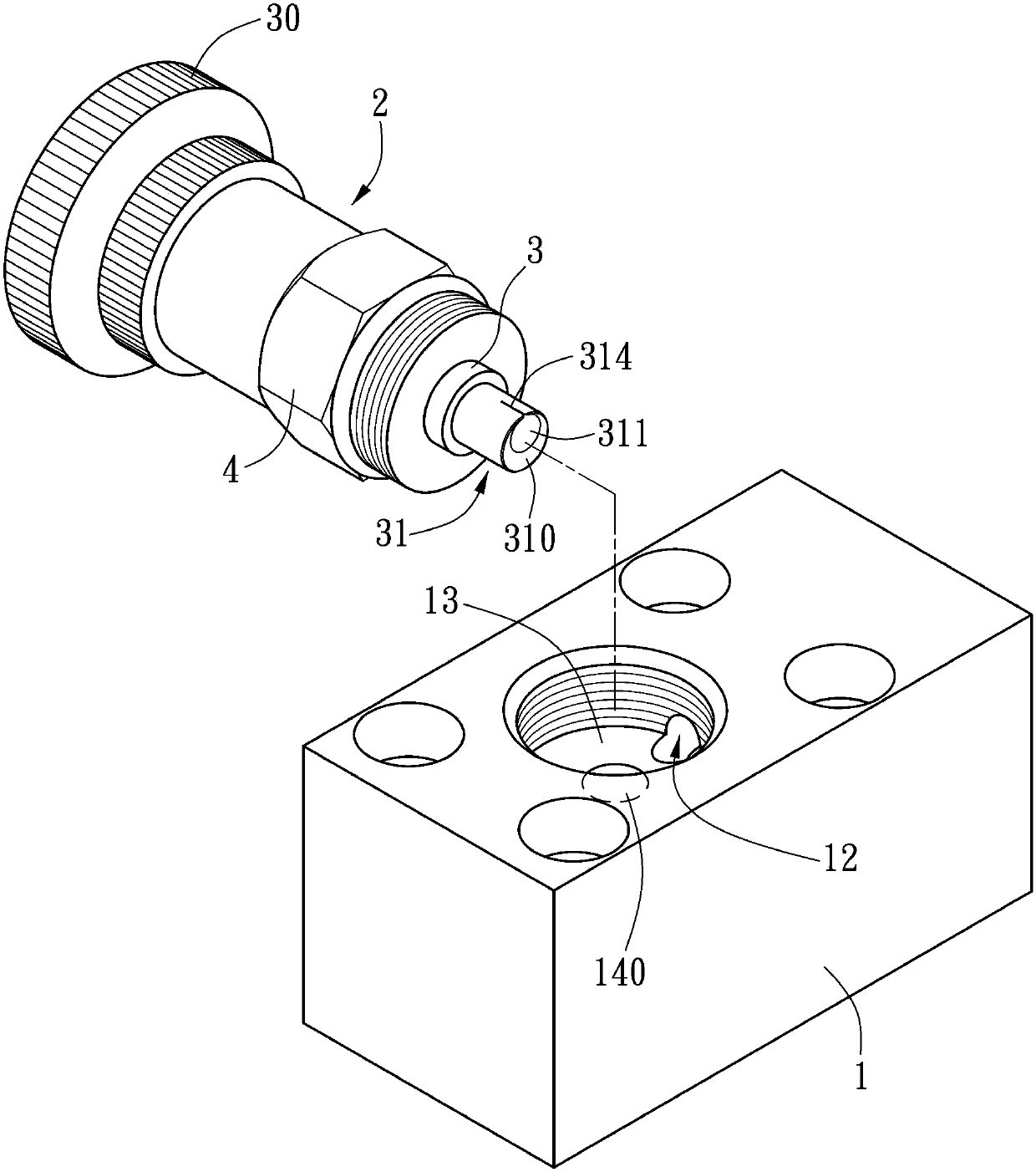
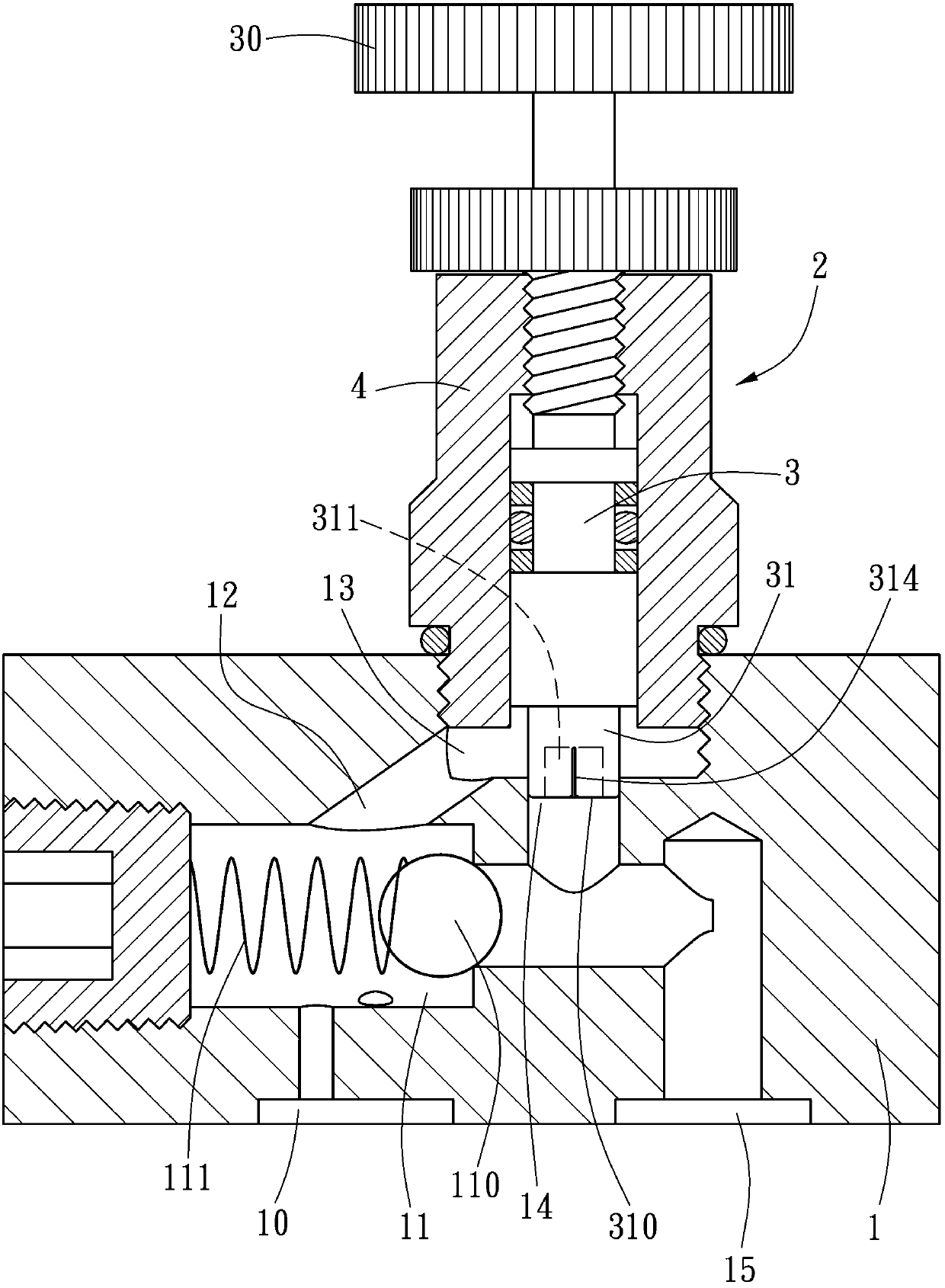
[0031] Such as image 3 As shown, the valve body 1 has a first port 10, a main flow passage 11, a first passage 12, a groove 13, a second passage 14 and a first port 15. The main flow passage 11, the first passage 12 and the second passage 14 are all hidden inside the valve body 1, and the first port 10, the tank 13 and the first port 15 respectively lead to the outs...


PUM


Abstract

The invention provides a flow control valve having a valve body and an adjusting member which is screwed in the valve body in an axially displaceable manner through a shaft. The shaft has a cylinder section at the end in the valve body, the diameter of the end face of the cylinder section is equal to that of an opening of a second channel. The end face of the cylinder section inserts in the opening to the second channel. The cylinder section has a slit which is inserted in the second channel to increase the length exposed in a slot chamber to control the flow of hydraulic oil running through the slit. When a flow control valve employs such a structure, the resistance of hydraulic oil running through the inner wall of the slit is relatively low, so that the stagnation problem is overcome compared with a known flow control valve. The flow of hydraulic oil is controlled to be stable.

Description

Technical field [0001] The invention relates to a flow control valve, in particular to a valve body structure of a flow control valve used in a hydraulic circuit to control the flow of hydraulic oil. Background technique [0002] Such as Figure 8 to Figure 10 Shown is a known flow control valve, including a valve body 8 and an adjusting member 9. The valve body 8 communicates with a first port 80, a main flow passage 81, a first passage 82, a chamber 83, a second passage 84, and a first port 80. Two ports 85, the adjusting member 9 is locked into the valve body 8 with its connecting seat 90, and is screwed into the connecting seat 90 with a shaft 91. The shaft 91 is exposed in the chamber 83 with a cone section 910. The end surface of the cone section 910 911 is smaller than the opening 840 of the second passage 84, and the shaft 91 can be axially displaced when the connecting seat 90 is rotated, so that the shaft 91 with its end surface 911 extends into the opening 840 into the ...

Claims


Application Information

Patent Timeline
Patent Type & Authority Applications(China)
IPC IPC(8): F15B13/02
Inventor 刘资丰
Owner 刘资丰
Why Eureka
Try Eureka