clutch booster

A booster and clutch technology, applied to clutches, mechanical equipment, etc., can solve the problems of friction plates that cannot be quantified in time to reflect the wear of friction plates, and achieve a reliable and practical structure

Inactive Publication Date: 2016-08-10
宁波神丰汽车部件有限公司
View PDF8 Cites 2 Cited by
  • Summary
  • Abstract
  • Description
  • Claims
  • Application Information

AI Technical Summary

Problems solved by technology

[0003] The purpose of the present invention is to overcome the disadvantage that the current clutch booster pump assembly has the function of automatically compensating the stroke of the push rod when the friction plate is worn, but it cannot quantify and reflect the wear of the friction plate in time so as to replace the friction plate that is about to fail in time. A clutch booster that can quantify and reflect the wear of friction plates in time so as to replace the friction plates that are about to fail in time

Method used


Image

  • clutch booster
  • clutch booster
  • clutch booster

Examples


Embodiment 1

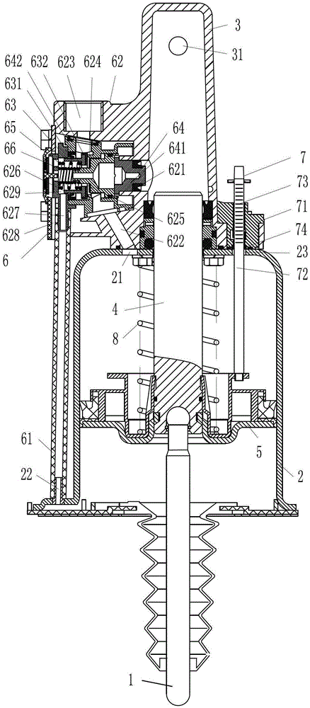
[0018] Embodiment 1, as attached figure 1 Shown: a clutch booster, including a pneumatic cylinder 2 with an air inlet 21 and an exhaust port 22 at the rear end and a front end respectively, a hydraulic cylinder 3 with a liquid inlet 31 connected to the rear end of the pneumatic cylinder 2, and a hydraulic cylinder 3 located at the air pressure Inside the cylinder 2, the two ends are respectively connected with the push rod 1 and the piston 5 of the piston rod 4 whose rear end extends into the hydraulic cylinder 3, the intake and exhaust control valve 6 set on the side wall of the hydraulic cylinder 3, and the friction plate wear measurement device 7 ; There is a return spring 8 between one end of the piston 5 and the pneumatic cylinder 2;

[0019] The friction lining wear measuring device 7 includes a slide bar seat 71 and a slide bar 72 screwed to the rear end of the air cylinder 2; The side circumference of the other end of the slide bar 72 has a dimension marking line 73; ...


PUM


Abstract

The invention relates to the field of automobile clutches, in particular to a clutch booster which comprises a pneumatic cylinder, a hydraulic cylinder, a piston of a piston rod, an intake and exhaust control valve and a friction plate wear measuring device. An air inlet and an air outlet are arranged at the rear end and the front end of the pneumatic cylinder respectively, the hydraulic cylinder is provided with a liquid inlet and connected with the rear end of the pneumatic cylinder, the piston is positioned in the pneumatic cylinder, two ends of the piston are connected with push rods respectively, the rear end of the piston extends into the hydraulic cylinder, the intake and exhaust control valve is arranged on the side wall of the hydraulic cylinder, and a reset spring is positioned between one end of the piston and the pneumatic cylinder. The clutch booster can timely and quantitatively reflect wear conditions of a friction plate, so that the friction plate about to lose effectiveness can be timely replaced.

Description

technical field [0001] The invention relates to the field of automobile clutches, in particular to a clutch booster. Background technique [0002] The utility model of Chinese Patent Announcement No. CN201989621U discloses an automobile clutch booster, comprising a clutch master cylinder, a clutch pedal and a clutch booster cylinder, the clutch master cylinder is connected to the clutch booster cylinder through a hydraulic actuation pipeline. The oil port is connected, and the air inlet of the clutch booster pump is connected to an air storage tank through the air pressure actuation pipeline, and the air storage tank is connected to an air compressor. arm. The clutch booster cylinder is the clutch booster; the clutch booster is a related device for the vehicle to control the vehicle by means of compressed air, high-pressure oil, etc., so as to achieve the purpose of easy operation when the clutch is disengaged. The utility model of Chinese patent announcement number CN 201...

Claims


Application Information

Patent Timeline
Patent Type & Authority Patents(China)
IPC IPC(8): F16D48/04
Inventor 徐文翁国畅
Owner 宁波神丰汽车部件有限公司
Why Eureka
Try Eureka