Optical detection system, biochemical analyzer, light beam orienting component and adjusting method of optical detection system and biochemical analyzer

An optical detection and beam technology, applied in the optical field, can solve the problem of large, some beams may be projected outside the sample under test or at the critical position between the sample and the container and be reflected or scattered, the test range of the sample under test is small, Affect the accuracy of test results and other issues, to achieve the effect of reducing the difficulty of system debugging, improving flexibility and convenience, and ensuring stability and accuracy

Active Publication Date: 2013-10-30
SHENZHEN MINDRAY BIO MEDICAL ELECTRONICS CO LTD
View PDF4 Cites 4 Cited by
  • Summary
  • Abstract
  • Description
  • Claims
  • Application Information

AI Technical Summary

Problems solved by technology

However, in some optical detection systems, especially micro-volume optical detection systems, due to the very small sample size, the allowable test range of the tested sample is small, and the projection area of ​​the beam converged by the converging projection component on the tested sample may be large , some light beams may be projected outsi

Method used


Image

  • Optical detection system, biochemical analyzer, light beam orienting component and adjusting method of optical detection system and biochemical analyzer
  • Optical detection system, biochemical analyzer, light beam orienting component and adjusting method of optical detection system and biochemical analyzer
  • Optical detection system, biochemical analyzer, light beam orienting component and adjusting method of optical detection system and biochemical analyzer

Examples


no. 1 example

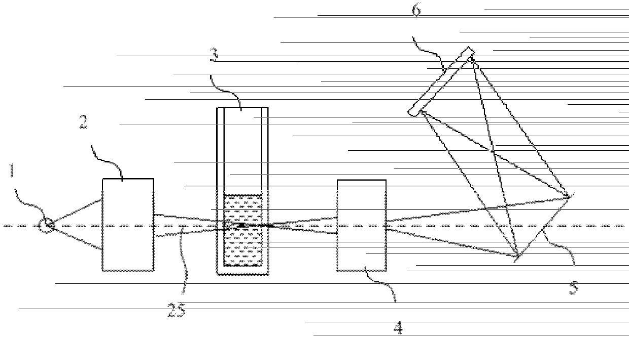
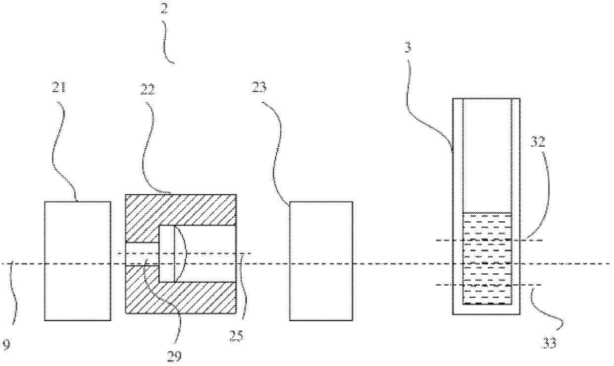
[0045] Such as Figure 1 to Figure 2 As shown, the optical detection system of an embodiment is used to detect the substance components contained in the sample to be tested, which includes a light source 1, a beam orientation component 2, a sample placement position 3, and a light beam arranged in sequence to form a direct light path. Collecting component 4, light splitting component 5 and photodetecting component 6. According to specific needs, each component can be installed on a base that realizes light path sealing, with a certain distance between adjacent components. The measured sample placement position 3 is used to place the measured sample. In this embodiment, the measured sample placement position 3 is located between the beam directing component 2 and the beam collecting component 4. In some embodiments, for example, the measured sample faces the beam In the case of reflection, the sample placement position 3 to be tested may also be located on one side of the beam ...

no. 2 example

[0057] Such as Picture 9 with Picture 10 As shown, the optical detection system of this embodiment includes a light source 1, the beam orientation component described in the first embodiment, a sample placement position 3, a beam collection component, a spectroscopic component, and a photodetection component, as well as a light path reflex component 24. The light path folding component 24 has a reflective surface 241. In this embodiment, the beam adjusting component 22 is located on the rear side of the light path folding component 24. The light incident surface of the light beam adjusting component 22 in the light source 1 and the beam directional component is the same as the reflecting surface 241. In contrast, after the light beam generated by the light source 1 is reflected by the reflecting surface 241, the incident light beam 41 is formed and enters the beam adjusting component 22. In some embodiments, the beam adjusting component 22 may also be located on the front side ...


PUM


Abstract

The invention discloses an optical detection system, a biochemical analyzer, a light beam orienting component and a light beam adjusting method of the optical detection system and the biochemical analyzer. The optical detection system comprises a light source, a light beam collecting component, a detected sample placing position and the light beam orienting component, wherein the light beam orienting component comprises a support and a light beam adjusting part, the light beam orienting component is provided with an incident surface and a light emitting surface which are respectively opposite to the light source and the light beam collecting component, the light beam adjusting part is fixed on the support, and an adjustable clearance and/or adjustable angle is formed between the light beam adjusting part and the support; and the detected sample placing position is located between the light beam orienting component and the light beam collecting component or located at one sides of the light beam orienting component and the light beam collecting component. In the invention, the optical axis of the light beam adjusting part can generate parallel excursion for a certain distance or deflection for a certain angle relative to the principal optical axis of an optical system, so that a light beam emitted by the light beam adjusting part is propagated along a reasonable direction to meet the working requirement of the optical system.

Description

Technical field [0001] The invention relates to the field of optics, in particular to an optical detection system, a biochemical analyzer, an adjustment method thereof, and a beam orientation component. Background technique [0002] Optical detection systems, optical scanning systems, optical projection systems and other optical systems generally converge, diverge, refract, reflect or other forms of directional processing on the incident light generated by the light source according to certain requirements, and then project it to the specified position for subsequent use However, during the working process of the optical system, it is affected by the parts precision and assembly precision, installation requirements, operation requirements, use conditions and other factors in the system. The beam direction after directional processing is sometimes difficult to meet the working requirements of the optical system, or may cause Poor use effect. [0003] For example, an optical detecti...

Claims


Application Information

Patent Timeline
IPC IPC(8): G01N21/17G02B7/02
Inventor 周洋
Owner SHENZHEN MINDRAY BIO MEDICAL ELECTRONICS CO LTD
Why Eureka
Try Eureka