Standby wake-up circuit and electronic device

A technology for waking up circuits and electronic devices. It is applied in the direction of adjusting electrical variables, electrical program control, and electrical digital data processing. It can solve the problems of large power consumption, increased standby power consumption, and shortened standby time, so as to extend standby time, Effect of Reducing Standby Power Consumption

Inactive Publication Date: 2013-10-30
HONG FU JIN PRECISION IND (SHENZHEN) CO LTD +1
View PDF0 Cites 15 Cited by
  • Summary
  • Abstract
  • Description
  • Claims
  • Application Information

AI Technical Summary

Problems solved by technology

[0003] However, when the electronic device is in a standby state, since the enable end of the voltage conversion chip is always kept at a high level, that is, the voltage conversion chip always supplies power to the processing chip, and since the processing chip is the core component of the electronic device, its The power consumption is large; keeping the processing chip always in the power supply state in the standby state will increase the standby power consumption and shorten the standby time

Method used


Image

  • Standby wake-up circuit and electronic device
  • Standby wake-up circuit and electronic device

Examples


Embodiment Construction

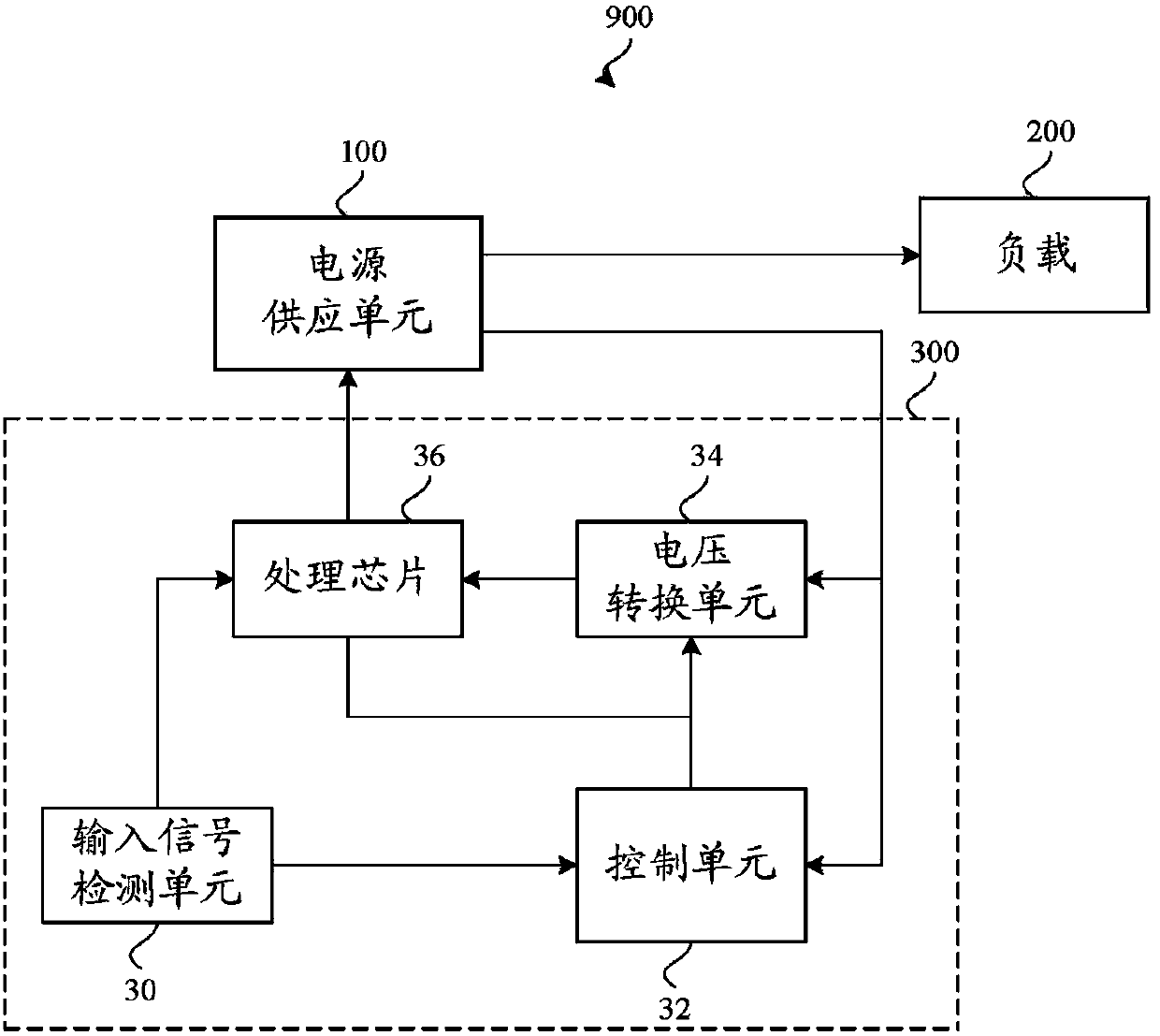
[0014] see figure 1 , an electronic device 900 in a preferred embodiment includes a power supply unit 100 , a load 200 and a standby wake-up circuit 300 , and the electronic device 900 can switch between a standby state and a working state. When the electronic device 900 is in the working state, the power supply unit 100 provides the main power supply voltage to the load 200 and provides the auxiliary power supply voltage to the standby wake-up circuit 300 . When the electronic device 900 is in the standby state, the power supply unit 100 stops providing the main power supply voltage to the load 200 and provides the auxiliary power supply voltage to the standby wake-up circuit 300 . The electronic device 900 can be a portable DVD player, a notebook computer, and the like.

[0015] The following part is described in the case that the electronic device 900 is in the standby state.

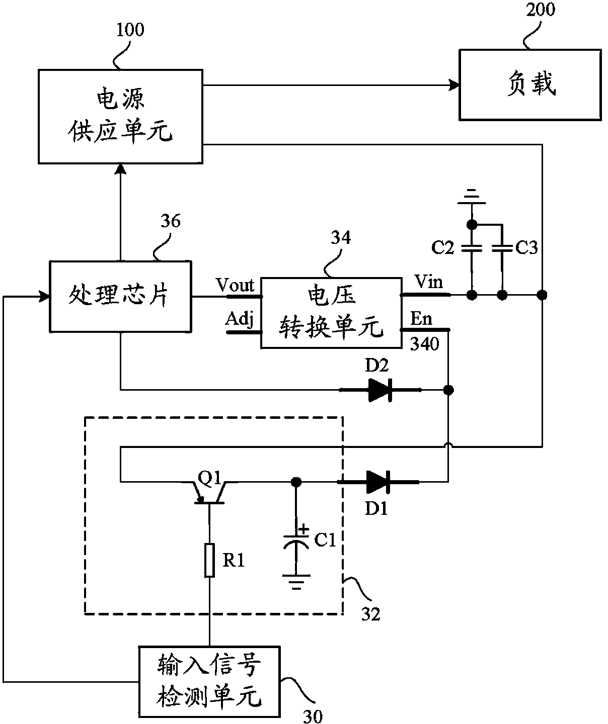
[0016] The standby wake-up circuit 300 includes an input signal detection unit 30 , a control u...


PUM


Abstract

A wake-up circuit (300) includes a receiving unit (30) receiving a wake-up signal, a control unit (32), a voltage converter (34), and a processing unit (36). The control unit (32) continuously generating an enable signal for a first predetermined time period when the receiving unit (30) receives the wake-up signal and stopping generating the enable signal after the first predetermined time period. The power supply (100) provides a secondary voltage to the voltage converter (34) when the electronic device (900) is in the standby state, and the voltage converter (34) converts the secondary voltage to a working voltage when the voltage converter (34) receives the enable signal and forgoes generating the working voltage when the voltage converter (34) fails to receive the enable signal. The processing unit (36) is powered by the working voltage to generate the enable signal and output the enable signal to the voltage converter (34), the processing unit (36) further generates a control signal when the processing unit (36) determines that the wake-up signal is a power-on command, the control signal controls the power supply (100) to power the load (200).

Description

technical field [0001] The invention relates to a standby wake-up circuit and an electronic device. Background technique [0002] The standby wake-up circuit is widely used in electronic devices such as DVD players. The above-mentioned standby wake-up circuit usually includes an input signal detection unit, a voltage conversion chip and a processing chip. The above-mentioned electronic device also includes a power supply unit and a load. The terminal provides an auxiliary power supply voltage, so that the voltage conversion chip converts the auxiliary power supply voltage received by the power supply terminal into an operating voltage, and provides the operating voltage to the processing chip to enable the processing chip to power on and work. The processing chip is used to control the power supply unit to provide the main power supply voltage to the load when the input signal detection unit receives an external trigger signal (such as an external trigger signal of a button...

Claims


Application Information

Patent Timeline
Patent Type & Authority Applications(China)
IPC IPC(8): G05B19/04
CPCG05F3/02G06F1/266
Inventor 马彬淞
Owner HONG FU JIN PRECISION IND (SHENZHEN) CO LTD
Why Eureka
Try Eureka