Interference suppression combining method and apparatus

A technology of interference suppression and noise interference, applied in the field of communication, can solve the problems of decreased data throughput, decreased real-time performance, and increased computational complexity of the system, and achieves the effects of reducing computational complexity, reducing computational complexity, and improving system throughput.

Active Publication Date: 2018-05-15
SANECHIPS TECH CO LTD
View PDF1 Cites 0 Cited by
  • Summary
  • Abstract
  • Description
  • Claims
  • Application Information

AI Technical Summary

Problems solved by technology

[0018] The present invention provides an interference suppression combining method and device, to at least solve the problem of increased computational complexity, reduced system data throughput, and reduced real-time performance caused by first performing channel estimation interpolation and then constructing a combined weight matrix for equalization in the prior art. technical issues

Method used


Image

  • Interference suppression combining method and apparatus
  • Interference suppression combining method and apparatus
  • Interference suppression combining method and apparatus

Examples


Embodiment 1

[0084] In this preferred embodiment, MMSE is taken as an example for illustration:

[0085] Such as Figure 6 Shown is a schematic diagram of a time-frequency structure of an uplink subframe in an LTE system. Wherein, one subframe includes two time slots. In the time domain, one slot includes 7 SC-FDMA (Single Carrier Frequency Division Multiple Access) symbols (1=0...6). In the frequency domain, each symbol occupies 1200 useful information subcarriers (k=0...1999). There are pilot symbols on the 4th symbol of slot 0 and the 4th symbol of slot 1, which are used to transmit the reference signal of UE (User Equipment).

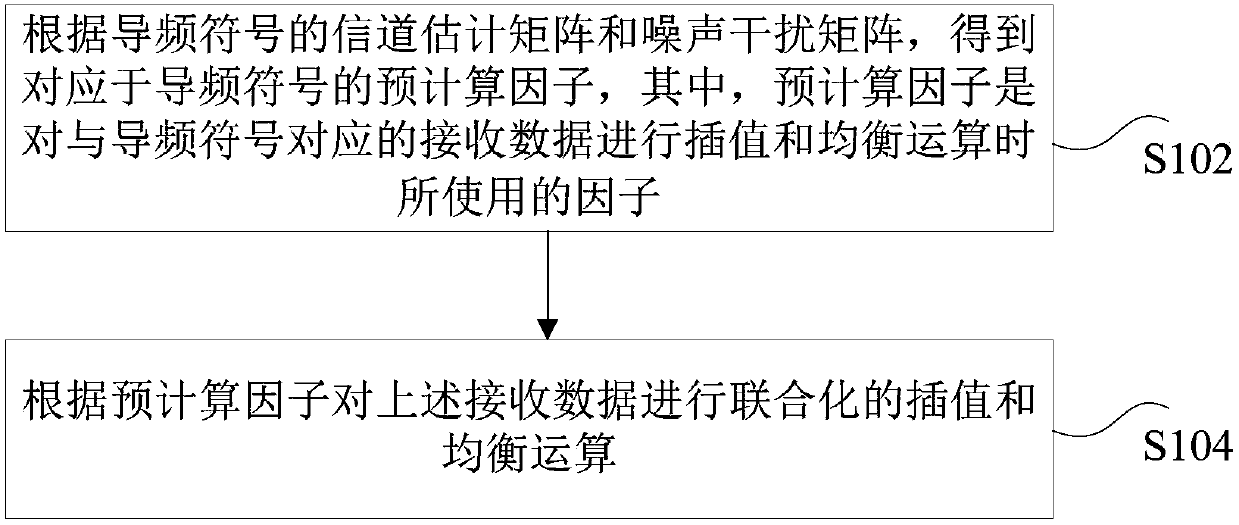
[0086] in accordance with Figure 6 The schematic diagram of the time-frequency structure is shown, and the method of IRC equalization method is carried out with the MMSE criterion, such as Figure 7 shown, including the following steps:

[0087] Step S702: Acquire channel estimation values ​​on pilot symbols.

[0088] Wherein, the above step S702 include...

Embodiment 2

[0139] In this preferred embodiment, the IRC merger of the SNR method is used as an example for illustration:

[0140] In this embodiment still as Figure 6 What is shown is a schematic diagram of a time-frequency structure of an uplink subframe in an LTE system for illustration.

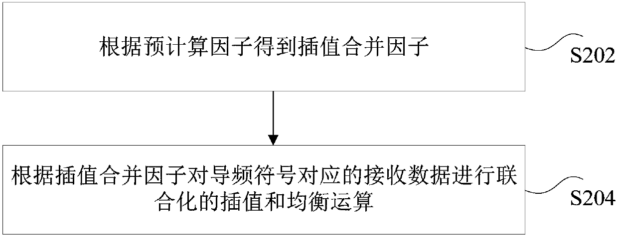
[0141] in accordance with Figure 6 The schematic diagram of the time-frequency structure shown, the method of IRC equalization with the SNR method, such as Figure 10 shown, including the following steps:

[0142] Step S1002: Obtain channel estimation values ​​on pilot symbols.

[0143] Wherein, the above step S1002 includes:

[0144] Obtain the rough channel estimate H on each subcarrier on the 2 pilot symbols C (i SLOT , l DMARS ,k,ka RX ) and the fine channel estimate H R (i SLOT , l DMARS ,k,ka RX ), where i SLOT =0, 1 is the time slot index, l DMARS =3, 10 is the index of the pilot time domain symbol, k=0,1...1199 is the frequency domain subcarrier index, ka RX =0,1...7 are rece...


PUM


Abstract

The present invention discloses an interference suppression combining method and device, wherein the method includes: obtaining a precalculation factor corresponding to the pilot symbol according to the channel estimation matrix and the noise interference matrix of the pilot symbol, wherein the precalculation factor is The factor used when performing joint interpolation and equalization operations on the received data corresponding to the pilot symbols; performing interpolation and equalization operations on the received data corresponding to the pilot symbols according to the pre-calculated factor. The present invention solves the technical problems of increasing the computational complexity caused by performing channel estimation interpolation first, and then constructing and combining the weight matrix for equalization in the prior art, and the system's data throughput rate decreases and real-time performance is reduced, and achieves the reduction of computational complexity , The technical effect of improving the system throughput and the real-time performance of data processing.

Description

technical field [0001] The present invention relates to the communication field, in particular to an interference suppression combining method and device. Background technique [0002] For cellular mobile communication systems, there is a big difference between the data rate at the center of the cell and the data rate at the edge of the cell, which not only limits the capacity of the entire system, but also makes the quality of service obtained by users at different locations very different. big difference. Currently, a new generation of broadband wireless communication systems being developed, such as Long Term Evolution (LTE for short) and Worldwide Interoperability for Microwave Access (Wimax for short), will improve cell edge performance as a system performance one of the main indicators. [0003] Moreover, in order to improve spectrum utilization and ensure the coexistence of cells with different communication standards, the LTE system will face more severe co-channel...

Claims


Application Information

Patent Timeline
Patent Type & Authority Patents(China)
IPC IPC(8): H04L25/02H04L25/03H04B7/08
Inventor 王鹏
Owner SANECHIPS TECH CO LTD
Why Eureka
Try Eureka