
LED dimming circuit and LED lamp

A dimming circuit and circuit technology, applied in the field of lighting, can solve the problems of unfavorable and effective use of energy, large useless power consumption, complex dimming circuit, etc., and achieve the effect of avoiding large energy loss and stable lighting

Inactive Publication Date: 2013-11-06
OCEANS KING LIGHTING SCI&TECH CO LTD +1
View PDF3 Cites 3 Cited by
  • Summary
  • Abstract
  • Description
  • Claims
  • Application Information

AI Technical Summary

Problems solved by technology

Most of the existing LED lamps cannot adjust the brightness, and usually can only be illuminated with one or two brightness levels set at the factory, which cannot meet people's diverse lighting needs
However, for a small number of LED lamps that can adjust the brightness, the dimming circuit is complicated, and the useless power consumption in the circuit is too large, which is not conducive to the effective use of energy.

Method used


Image

  • LED dimming circuit and LED lamp

Examples


Embodiment Construction

[0017] The following will clearly and completely describe the technical solutions in the embodiments of the present invention with reference to the accompanying drawings in the embodiments of the present invention. Obviously, the described embodiments are only some, not all, embodiments of the present invention. Based on the embodiments of the present invention, all other embodiments obtained by persons of ordinary skill in the art without creative efforts fall within the protection scope of the present invention.

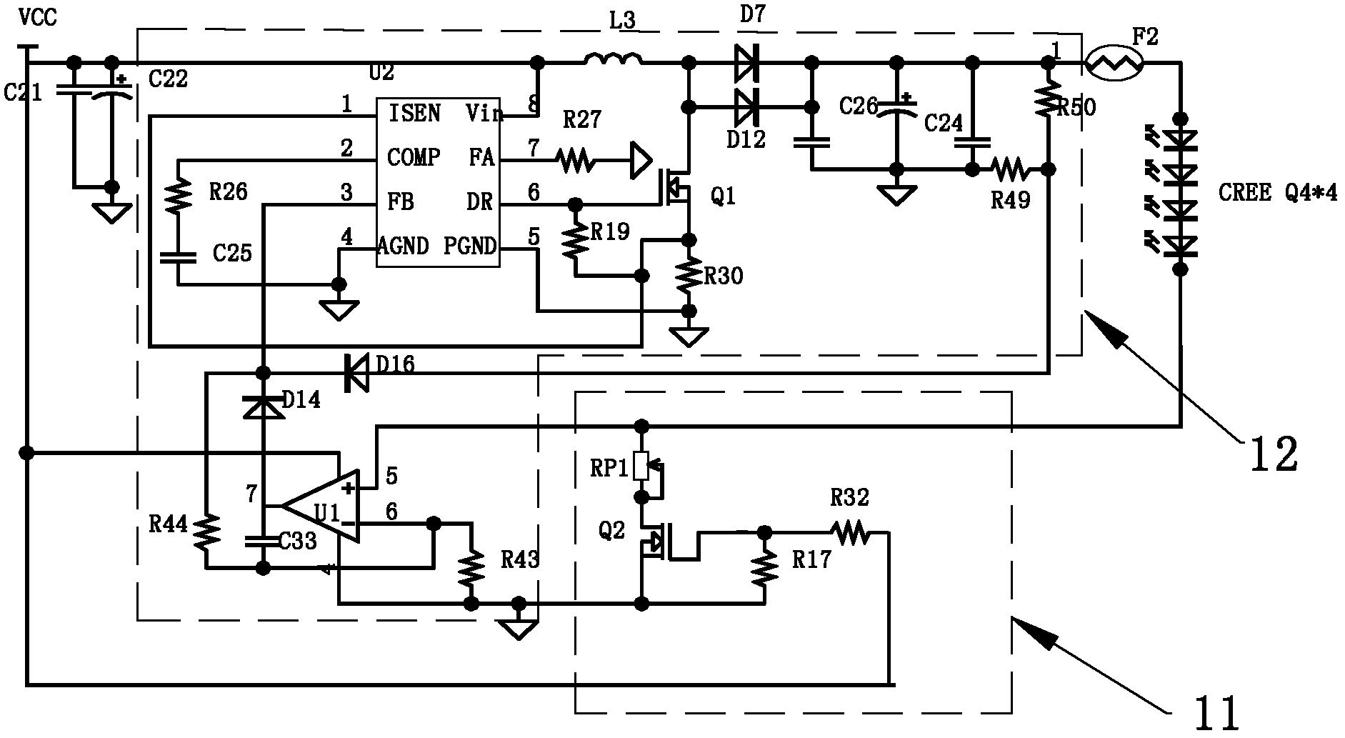
[0018] Embodiments of the present invention will be described below with reference to the accompanying drawings. see figure 1 , is a structural schematic diagram of an embodiment of the LED dimming circuit of the present invention.

[0019] Wherein, the LED dimming circuit includes an adjustment control module 11 and a voltage stabilization module 12, the adjustment control module 11 includes a current detection potentiometer RP1, and the current detection potenti...


PUM


Abstract

The invention discloses an LED dimming circuit which comprises an adjusting control module and a voltage stabilizing module. The adjusting control module comprises a current detecting potentiometer which is connected with an LED loader and used for adjusting the brightness of the LED loader. The voltage stabilizing module comprises a voltage comparer U1 and a voltage stabilizing control chip U2, wherein the normal phase input end of the voltage comparer U1 is connected with the current detecting potentiometer, the output end of the voltage comparer U1 is connected with the voltage stabilizing control chip U2 to be used for feeding adjustment of the current detecting potentiometer back to the LED loader through the voltage stabilizing control chip U2, and the voltage stabilizing control chip U2 is used for adjusting and stabilizing voltage at the two ends of the LED loader according to the electrical level of the output end of the voltage comparer U1. The invention further discloses an LED lamp. The LED dimming circuit can stably adjust the brightness of the LED loader, meets various requirements of people, guarantees that a light source is stable and free of flickering when being adjusted, reduces energy loss caused by resistance heating and improves energy utilization rate.

Description

technical field [0001] The invention relates to the lighting field, in particular to an LED dimming circuit and an LED lamp. Background technique [0002] As a new light source, LED has the characteristics of energy saving, environmental protection and high efficiency, and has been widely used in various lighting fields. Most of the existing LED lamps cannot adjust the brightness, and usually can only be illuminated with one or two brightness levels set at the factory, which cannot meet people's diverse lighting needs. However, for a small number of LED lamps that can adjust the brightness, the dimming circuit is complicated, and the useless power consumption in the circuit is too large, which is not conducive to the effective use of energy. Contents of the invention [0003] The technical problem to be solved by the present invention is to provide an LED dimming circuit and an LED lamp. It can meet people's diverse lighting needs and improve energy efficiency. [0004]...

Claims


Application Information

Patent Timeline
IPC IPC(8): H05B37/02
Inventor 周明杰王现中
Owner OCEANS KING LIGHTING SCI&TECH CO LTD
Learn More