Liquid cooled motor

A liquid-cooled motor and liquid-cooled technology, applied in the direction of electrical components, electromechanical devices, electric components, etc., can solve the problems of inability to realize circulating cooling, reduced cooling efficiency of liquid cooling devices, and inconvenient cleaning of flow channels, etc.

Inactive Publication Date: 2013-11-13
NINGBO TENGLONG OUTDOOR IMPLEMENT
View PDF4 Cites 3 Cited by
  • Summary
  • Abstract
  • Description
  • Claims
  • Application Information

AI Technical Summary

Problems solved by technology

The diameter of the flow channel is not very large due to space constraints. When the motor is used for a period of time, a thick scale will accumulate in the flow channel, which will block the flow channel and make it impossible to achieve circulating cooling; It will also prevent the cooling water from directly and fully contacting the motor casing, because the scale is attached to the surface of the motor casing, and it is easy to form a structure similar to the insulation layer, resulting in a decrease in the cooling efficiency of the liquid cooling device. The occurrence of the above two situations makes the user The flow channel in the water cooling device needs to be cleaned frequently, and the entire motor casing and water cooling device cannot be disassembled. If chemical methods are used to clean the scale, the motor casing and cooling device will be corroded, so often only the entire motor casing and water cooling device can be replaced
Similarly, if it is an oil cooling device, the cooling oil often contains various impurities, and the impurities in the oil will block the cooling flow channel during the use of the motor. At this time, the cooling device needs to be removed for cleaning. The oil cooling device cannot be disassembled, and the user can only replace the entire motor casing and oil cooling device
To sum up, the liquid-cooled motors in the prior art have the disadvantages that the flow channel of the cooling device is inconvenient to clean, and the flow channel is easily blocked.

Method used


Image

  • Liquid cooled motor
  • Liquid cooled motor
  • Liquid cooled motor

Examples


Embodiment Construction

[0014] The present invention will be described in further detail below in conjunction with the accompanying drawings.

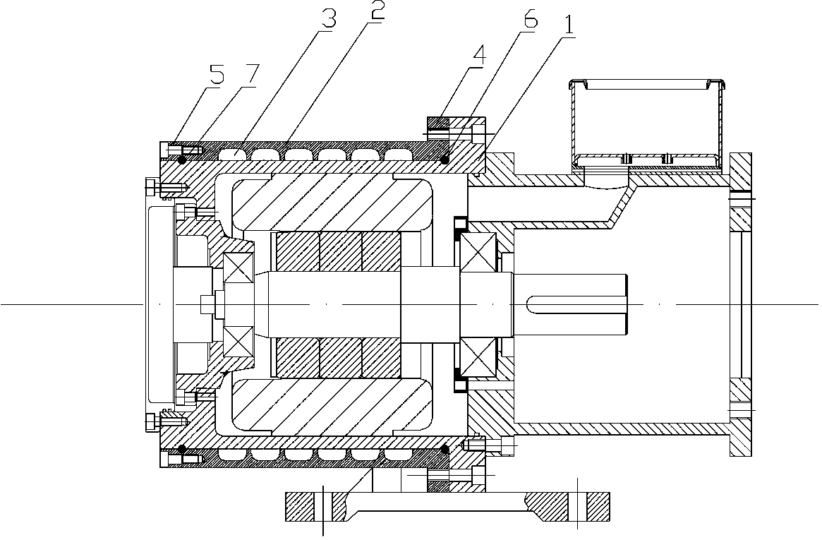
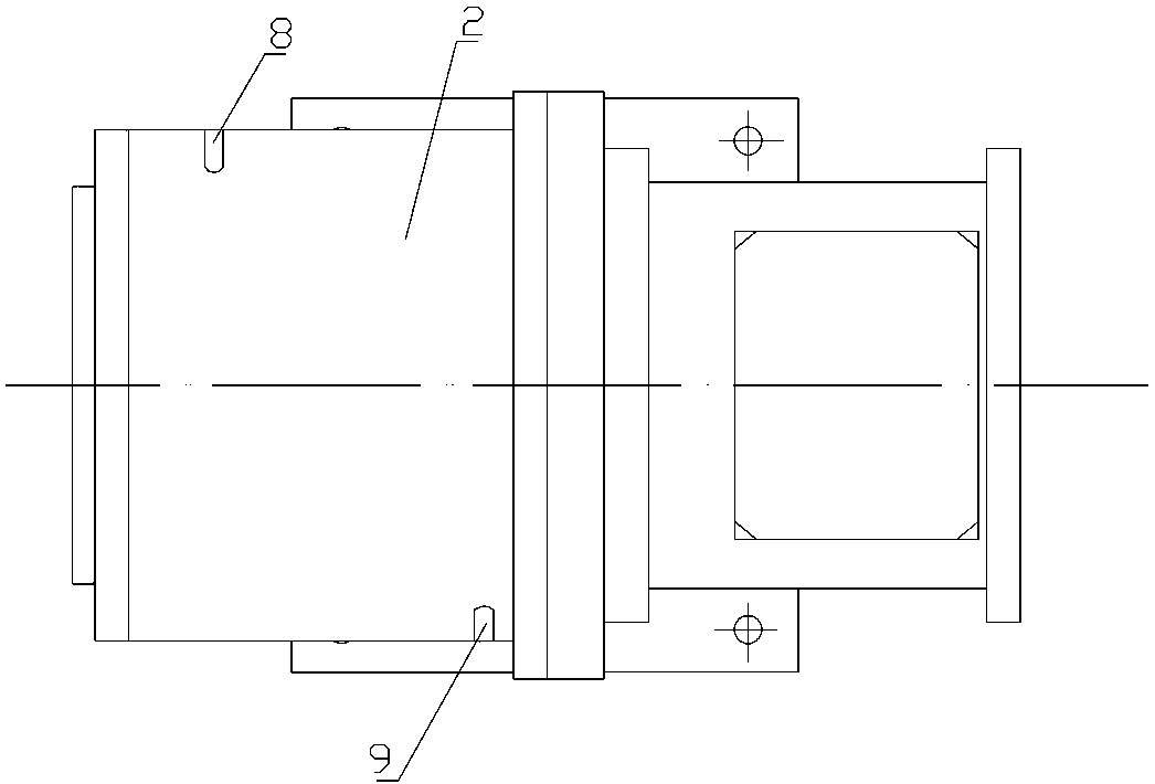
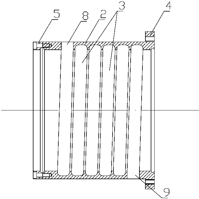
[0015] combined with figure 1 to attach Figure 4 , a liquid-cooled motor, which includes a motor housing 1, a liquid cooling device 2 is installed on the motor housing, the liquid cooling device 2 is detachably connected to the motor housing 1, and the detachable connection It means that the liquid cooling device 2 is a cover body with an annular hole nested with the motor casing 1, and the annular hole wall of the cover body is provided with a grooved flow channel 3, and the flow channel 3 communicates with There is a liquid inlet 8 and a liquid outlet 9, and one end of the cover body is provided with a connector 4 for connecting with the motor casing 1; the junction of the connector 4 and the motor casing 1 is provided with a first sealing ring 6; The other end is sealingly connected with the motor casing 1 . The grooved flow channel 3 has a spiral stru...


PUM


Abstract

The invention provides a liquid cooled motor. According to the liquid cooled motor, runners of a cooling device can be cleaned conveniently, and runner blockage cannot be easily caused. The liquid cooled motor comprises a motor casing (1), and a liquid cooled device (2) is mounted on the motor casing. The liquid cooled motor is characterized in that the liquid cooled device (2) is a cover body with an annular hole sleeved with the motor casing (1), groove type runners (3) are arranged in the annular hole wall of the cover body, a liquid inlet (8) and a liquid outlet (9) are communicated onto the runners (3), and a connector (4) for being connected with the motor casing (1) is arranged at one end of the cover body; a first sealing ring (6) is arranged at the junction of the connector (4) and the motor casing (1); the other end of the cover body is in sealing connection with the motor casing (1).

Description

technical field [0001] The invention relates to a liquid-cooled motor. Background technique [0002] In the prior art, in order to reduce the temperature rise of the motor and ensure the normal and stable operation of the motor, most motors are equipped with cooling devices, and the cooling devices are generally divided into two types: air cooling and liquid cooling. Air-cooled devices are not widely used due to their high noise and low cooling efficiency. Liquid cooling devices are widely used due to their quietness and high cooling efficiency. The liquid cooling devices used in the liquid-cooled motors in the prior art are all fixed on the casing of the motor by adopting a direct integrated structure. The two most commonly used installation methods are thermal sleeve and welding. The so-called thermal sleeve is to heat the cooling device to expand it and put it on the motor casing, and then let it cool to shrink it so that it can be fixed on the motor casing; welding is ...

Claims


Application Information

Patent Timeline
Patent Type & Authority Applications(China)
IPC IPC(8): H02K9/193
Inventor 刘坚
Owner NINGBO TENGLONG OUTDOOR IMPLEMENT
Why Eureka
Try Eureka