Construction machine with working attachment

A technology of construction machinery and operating devices, which is applied in the direction of mechanical equipment, fluid pressure actuating devices, mechanically driven excavators/dredgers, etc., and can solve problems such as pressure increase and pressure loss on the side of the rod

Active Publication Date: 2013-11-13
KOBELCO CONSTR MASCH CO LTD
View PDF8 Cites 10 Cited by
  • Summary
  • Abstract
  • Description
  • Claims
  • Application Information

AI Technical Summary

Problems solved by technology

However, this technique involves shrinking the oil chamber from the rod side of the boom cylinder back to the oil tank in order to increase the pressure on the rod side of the boom cylinder to a pressure that can be used as the p

Method used


Image

  • Construction machine with working attachment
  • Construction machine with working attachment
  • Construction machine with working attachment

Examples


Embodiment Construction

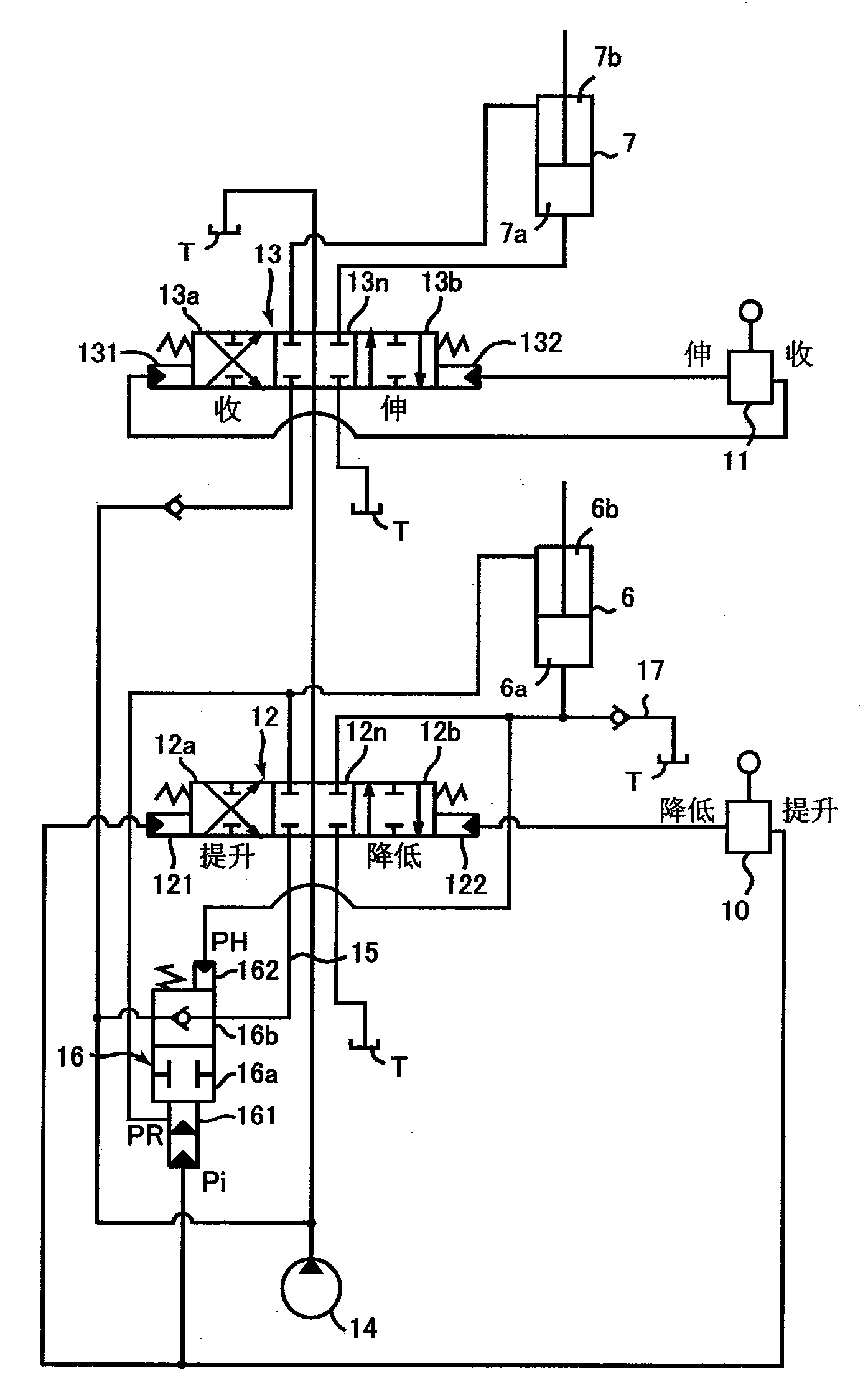
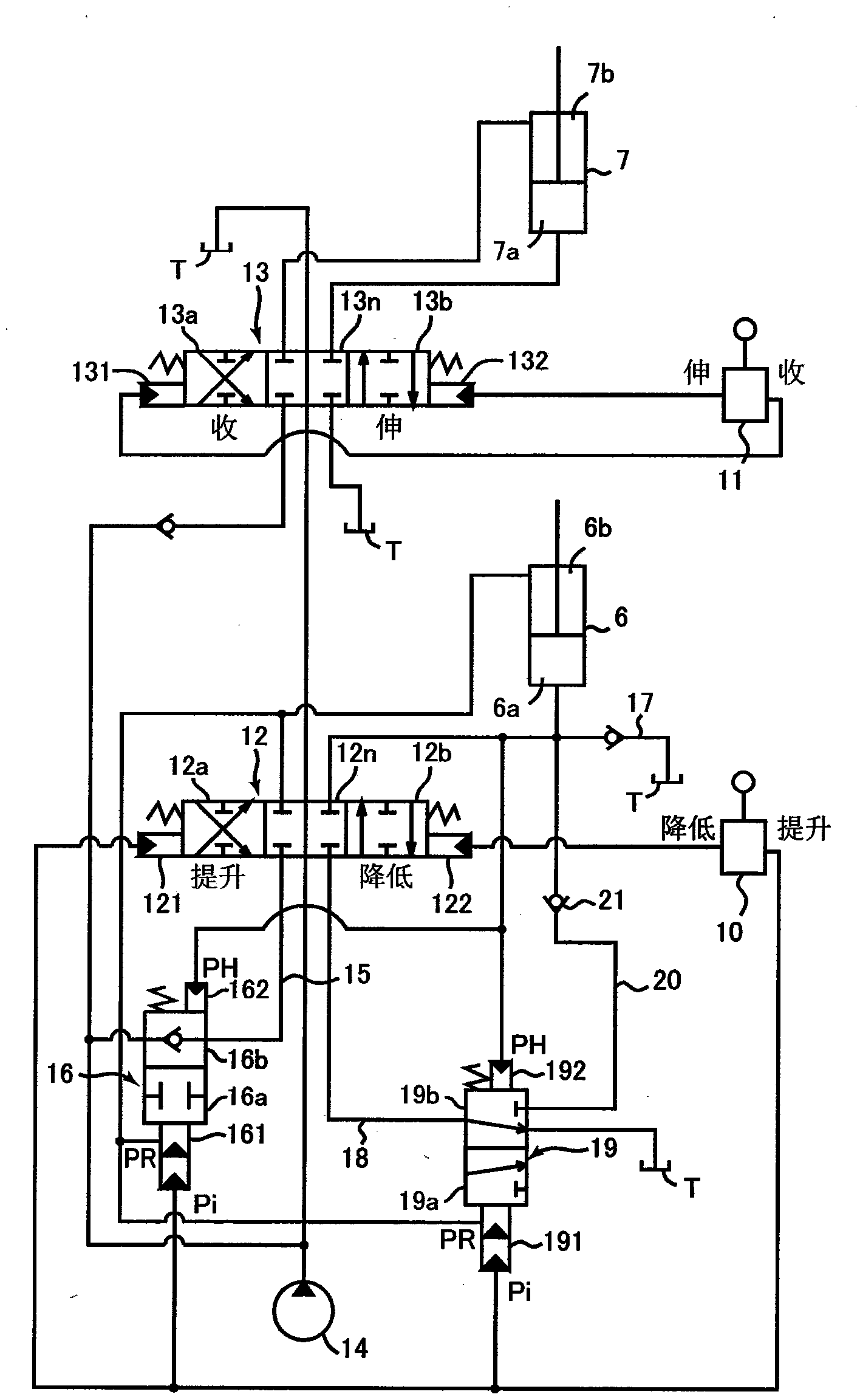
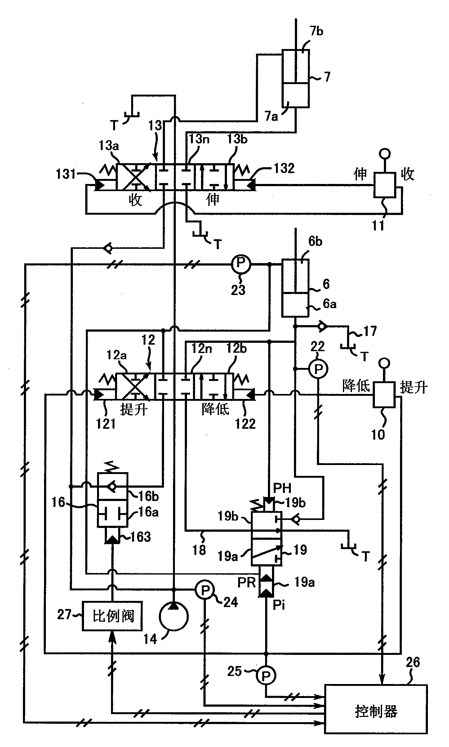
[0020] Embodiments of the present invention will be described with reference to the drawings. These implementations are based on Figure 5 The shown hydraulic excavator is used as the applicable object, and the hydraulic excavators respectively corresponding to the first to third embodiments are mounted on it. Figure 1 ~ Figure 3 The hydraulic circuit shown, wherein, the hydraulic excavator includes a lower walking body 1, an upper slewing body 2 and an operation attachment, the operation attachment has a boom 3, a stick 4 installed on the top of the boom 3, as The bucket 5 of the working device installed on the top end of the arm 4, the boom hydraulic cylinder 6 that drives the boom 3, the arm hydraulic cylinder 7 that drives the arm, and the working tool that drives the bucket 5 Bucket hydraulic cylinder 8 of the hydraulic cylinder. These embodiments will be described using, as an example, the control at the time of excavation work by combined operations of retracting the ...


PUM


Abstract

A construction machine, including: a hydraulic pump; a working attachment including a boom, a boom cylinder, and another fluid-supplied cylinder closer to a leading end than the boom cylinder; first and second operation devices for the boom cylinder and the fluid-supplied cylinder; first and second control valves; a flow-rate-limiting section; and an anti-cavitation circuit. The fluid-supplied cylinder receives fluid-supply from the hydraulic pump, together with the boom cylinder. A reaction force upon work accompanying extension of the fluid-supplied cylinder increases the rod-side pressure of the boom cylinder and reduces a head-side pressure. The flow-rate-limiting section limits a supply flow rate to a head-side fluid chamber of the boom cylinder only during a boom-raising-operation with the rod-side pressure higher than the head-side pressure in the boom cylinder. The anti-cavitation circuit replenishes hydraulic fluid from a tank to the head-side fluid chamber.

Description

technical field [0001] The present invention relates to a construction machine including a working attachment such as a hydraulic excavator. Background technique [0002] In a construction machine equipped with a working attachment, the working attachment has a boom, an arm, a working device, a boom hydraulic cylinder for driving the boom, an arm hydraulic cylinder for driving the arm, and an arm hydraulic cylinder for driving the arm. A work hydraulic cylinder of a work device in which a reaction force during work acts on the work attachment in a direction in which the boom cylinder is extended, whereby there is a rod-side oil chamber (rod-side oil chamber) of the boom cylinder. The pressure of the side fluid chamber (hereinafter referred to as the rod-side pressure (rod-side pressure)) increases, and the pressure of the head-side fluid chamber (hereinafter referred to as the head-side pressure (head-side pressure)) falling situation. [0003] use Figure 5 This will be d...

Claims


Application Information

Patent Timeline
IPC IPC(8): E02F9/22F15B11/02F15B11/08F15B21/14
CPCE02F9/2285E02F3/435E02F9/226F15B2211/329E02F9/2228E02F9/2282E02F9/2203F15B2211/3116E02F9/2029E02F3/30F15B21/14
Inventor 冈秀和
Owner KOBELCO CONSTR MASCH CO LTD
Why Eureka
Try Eureka