Rebuilding locking maxillofacial bone plate

A bone plate and maxillofacial technology, applied in the direction of outer plate, fixator, internal bone synthesis, etc., can solve the problems of cumbersome operation, prolong operation time, affect blood supply, etc., to simplify operation steps, improve operation efficiency, and shorten operation time. Effect

Active Publication Date: 2013-11-20
SHUANGYANG MEDICAL INSTR SUZHOU
View PDF6 Cites 10 Cited by
  • Summary
  • Abstract
  • Description
  • Claims
  • Application Information

AI Technical Summary

Problems solved by technology

Before the mandibular reconstruction and repair operation, the maxillofacial bone plate needs to be shaped according to the model of the patient's mandible with special plastic pliers to fit the patient's mandible so as to achieve a good reconstruction effect; this maxillofacial bone plate The disadvantages of the plate are: on the one hand, during the preoperative shaping process of the above-mentioned maxillofacial bone plate, the locking screw hole is easily deformed, resulting in poor mutual locking effect between the locking screw and the maxillofacial bone plate, so the above-mentioned maxillofacial bone plate Before the preoperative forming of the bone plate, a stuffing nail needs to be pre-placed in the locking screw hole, and then the stuffing nail is taken out after it is formed. The operation is cumbersome, which reduces the operation efficiency and prolongs the operation time; After the maxillofacial bone plate is locked and fixed by the screw, the top surface of the locking screw is higher than the top surface of the maxillofacial bone plate. Because the maxillofacial cortex is thin, it not only stimulates the soft tissue greatly, affects the blood supply, but also makes the postoperative The patient has a foreign body sensation

Method used


Image

  • Rebuilding locking maxillofacial bone plate
  • Rebuilding locking maxillofacial bone plate
  • Rebuilding locking maxillofacial bone plate

Examples


Embodiment Construction

[0012] The present invention will be further described below in conjunction with the accompanying drawings and specific embodiments.

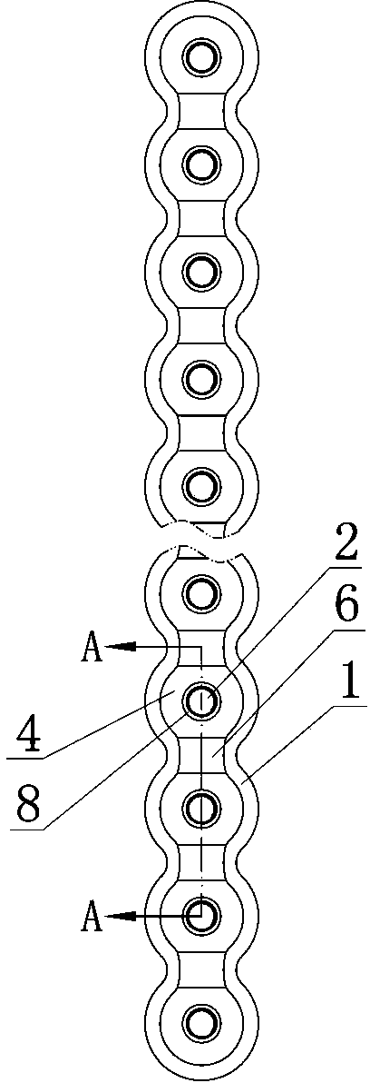
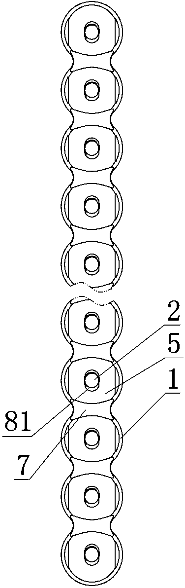
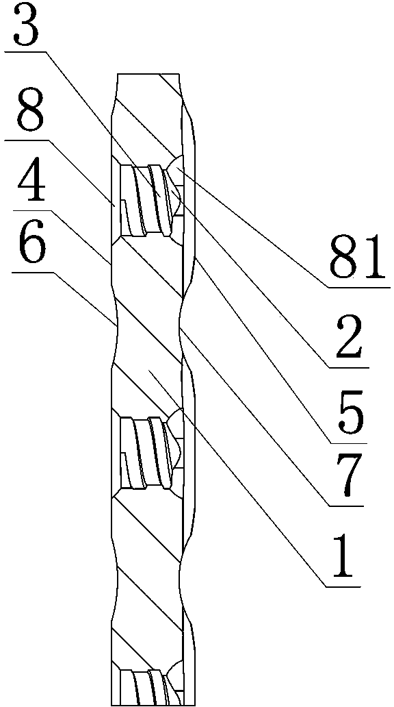
[0013] Such as figure 1 , figure 2 , image 3 , Figure 4 As shown, the locking and maxillofacial reconstruction bone plate includes a maxillofacial bone plate body 1, along the length direction of the maxillofacial bone plate body 1, a number of locking screw holes are evenly spaced on the maxillofacial bone plate body 1 2. Since the structure of each locking screw hole is the same, the following only uses the structure of one of the locking screw holes as an example to illustrate: the locking screw hole 2 is set with a diameter that gradually decreases from top to bottom, and runs through the body of the maxillofacial bone plate 1. There is an internal thread 3 in the locking screw hole 2, and the thread outer diameter of the internal thread 3 is the same as the maximum diameter of the locking screw hole 2; the maxillofacial bone plate bo...


PUM


Abstract

The invention discloses a rebuilding locking maxillofacial bone plate comprising a maxillofacial bone plate body. A plurality of locking screw holes are uniformly formed in the maxillofacial bone plate at intervals along the length of the maxillofacial bone plate body; each locking screw hole is reduced from top to bottom gradually and runs through the maxillofacial bone plate body and is provided with an internal thread, and the outer diameter of the internal thread is equal to the maximum diameter of the locking screw hole. An upper groove and a lower groove are respectively formed on the upper surface and the lower surface of the maxillofacial bone plate body between each two optional adjacent locking screw holes and are in up-and-down corresponding distribution; the upper groove runs through the upper surface of the maxillofacial bone plate body between the two optional adjacent locking screw holes, while the lower groove runs through the lower surface of the maxillofacial bone plate body between the two optional adjacent locking screw holes. The rebuilding locking maxillofacial bone plate is convenient to operate and has no deformation of locking screw holes during preoperative forming.

Description

technical field [0001] The invention relates to the field of medical instruments, in particular to a locking maxillofacial reconstruction type bone plate used for reconstruction and repair of mandible. Background technique [0002] After the mandible is resected due to tumor lesions, or is fractured by external impact, mandibular reconstruction and repair surgery is required. Maxillofacial bone plate is a commonly used medical device in mandibular reconstruction and repair surgery. The structure of the currently used maxillofacial bone plate is: comprising a maxillofacial bone plate body, along the length direction of the maxillofacial bone plate body, a number of locking screw holes are arranged at intervals on the maxillofacial bone plate. Before the mandibular reconstruction and repair operation, the maxillofacial bone plate needs to be shaped according to the model of the patient's mandible with special plastic pliers to fit the patient's mandible so as to achieve a good...

Claims


Application Information

Patent Timeline
Patent Type & Authority Applications(China)
IPC IPC(8): A61B17/80
Inventor 钱建清
Owner SHUANGYANG MEDICAL INSTR SUZHOU
Why Eureka
Try Eureka