
Central shaft device of steam type rapid boiling solid separator

A technology of solid separation and central axis, which is applied in the direction of solid separation, separation of solids from solids by air flow, chemical instruments and methods, etc. It can solve the problems of user loss, powder cannot be discharged as required, and cannot produce boiling requirements, etc. , to achieve the effect of uniform solid boiling, good sealing and high strength

Active Publication Date: 2015-09-23
浙江镇田机械有限公司
View PDF7 Cites 0 Cited by
  • Summary
  • Abstract
  • Description
  • Claims
  • Application Information

AI Technical Summary

Problems solved by technology

[0002] In the food and pharmaceutical powder particle steaming and washing equipment, the existing device is designed to adopt the nozzle type around the interior, and the steam inlet switch valve adopts a side-inserted type separator with a filter screen. Its structure cannot meet the boiling requirements, so that the internal powder After the steam enters, all of them are concentrated in one fast, and the boiling requirements cannot be produced, so that the powder cannot be discharged as required, which brings losses to the user.

Method used


Image

  • Central shaft device of steam type rapid boiling solid separator
  • Central shaft device of steam type rapid boiling solid separator
  • Central shaft device of steam type rapid boiling solid separator

Examples


Embodiment Construction

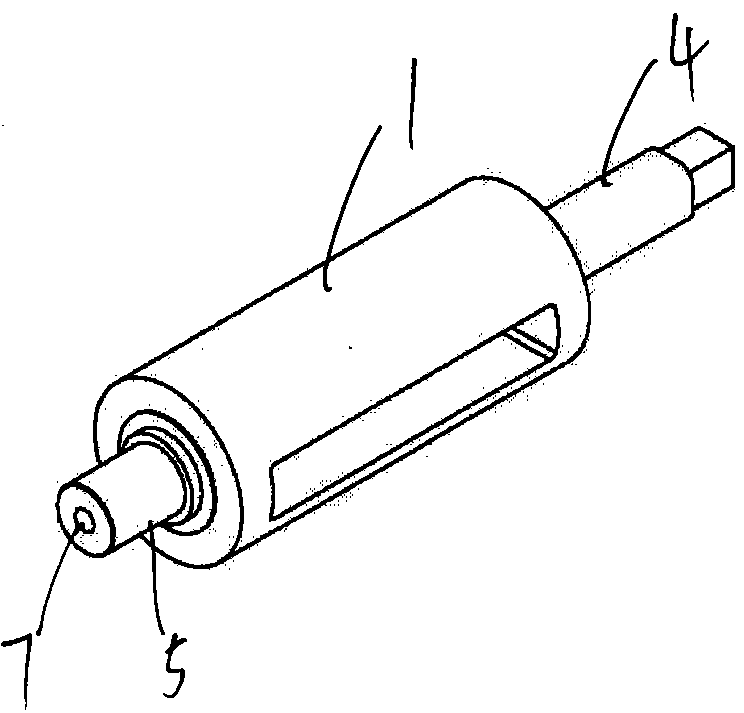
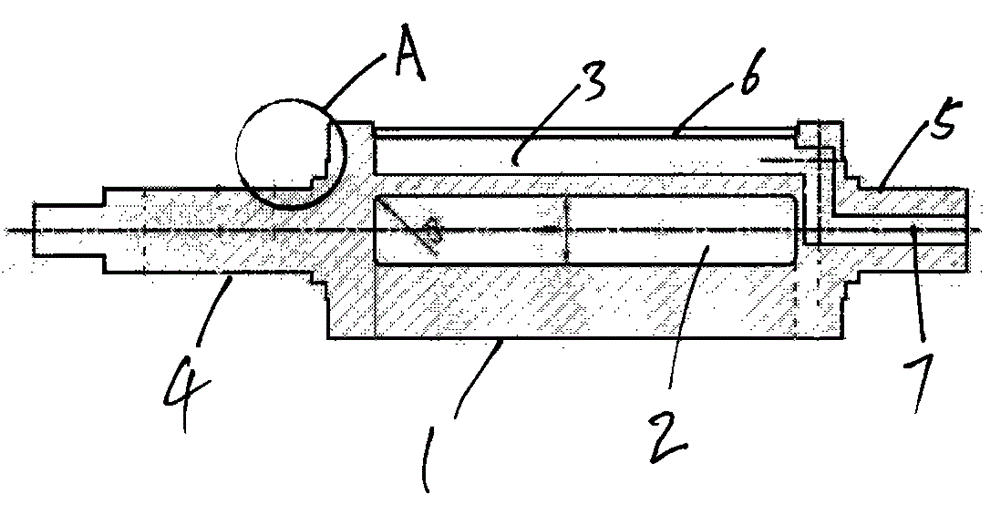
[0010] As shown in the figure, the central axis 1 is a metal cylinder. The central axis 1 is installed in the solid separation body to rotate 180°. There is a discharge bin 2 under the central axis 1. Under the operation of the intelligent control element, the central axis is switched 180° to make the central axis The discharge bin 2 corresponds to the discharge port of the solid separator. The two outlets are the same size to achieve fast discharge; the steam chamber 3 is arranged on the central axis, and the sintered mesh 6 is arranged above the steam chamber 3. When steam is used, the central axis Turn 180° so that the steam chamber port corresponds to the feed port of the solid separator. The steam quickly fills the steam chamber of the valve core, and enters the feed port of the solid separator evenly through the sintered mesh 6. The steam blows directly to the solid in the feed port. To make the solid boil quickly, the two ports have the same size, and the discharge bin 2...


PUM


Abstract

The invention discloses a central shaft device of a steam quick-boiling solid separator. The central shaft device comprises a central shaft, a discharge bin, a steam bin, a long rolling mandrel, a short rolling mandrel and an air inlet hole. The central shaft is a metal cylinder, is mounted in a solid separator body and only rotates within a 180-degree range in a reciprocating manner, the discharge bin is arranged at the lower edge of the central shaft, the steam bin is arranged at the upper edge of the central shaft, a sintered net is arranged above the steam bin, a structure is formed by the discharge bin and the steam bin in a body of the central shaft, and the discharge bin and the steam bin correspond to each other but are not communicated with each other in the structure; the rolling mandrels are arranged at the left end and the right end of the central shaft, the long rolling mandrel is arranged at one end of the central shaft and is a solid mandrel, the short rolling mandrel is arranged at the other end of the central shaft, the diameters of the two rolling mandrels are identical, the thicknesses of the walls at the left end and the right end of the central shaft are identical, a through hole is formed in the inner center of a body of the short rolling mandrel and is connected with the steam bin, and steps are arranged at joints of the left end and the right end of the central shaft and the rolling mandrels. The central shaft device has the advantages that solid can be boiled uniformly, and the central shaft device is good in sealing performance.

Description

Technical field: [0001] The invention relates to a central shaft device of a discharge machine, in particular to a central shaft device of a steam type fast boiling solid separator, and a control structure for directly entering steam from the central shaft to achieve rapid boiling solid separation. Background technique: [0002] In the food and pharmaceutical powder particle steaming and washing equipment, the existing device is designed to adopt the nozzle type around the interior, and the steam inlet switch valve adopts a side-inserted type separator with a filter screen. Its structure cannot meet the boiling requirements, so that the internal powder After the steam enters, all of them are concentrated in one fast, and the boiling requirement cannot be produced, so that the powder cannot be discharged as required, which brings losses to the user. Invention content: [0003] Aiming at the technical deficiencies of the existing above-mentioned products, the object of the p...

Claims


Application Information

Patent Timeline
Patent Type & Authority Patents(China)
IPC IPC(8): B07B7/00B07B11/06
Inventor 马月鲤项光增项光武万信林王彦红冯治聪
Owner 浙江镇田机械有限公司
Learn More