
A short-range take-off and landing UAV without power-driven rotor

A short-range take-off and landing, unmanned aerial vehicle technology, applied in the direction of rotorcraft, motor vehicles, aircraft, etc., can solve the problems of the complex structure of the rotor-type unmanned aerial vehicle, the difficulty of accurately controlling the landing site, and the limitation of the use range of the unmanned aerial vehicle, etc. Achieve the effect of enhancing the lateral heading stability, reducing the interference resistance of the wing body, and increasing the lateral heading stability

Active Publication Date: 2016-03-02
CHINA ACAD OF AEROSPACE AERODYNAMICS
View PDF5 Cites 0 Cited by
  • Summary
  • Abstract
  • Description
  • Claims
  • Application Information

AI Technical Summary

Problems solved by technology

Hand-throwing and catapult take-off are limited by the strength of the personnel's arms and the thrust of gunpowder and springs, which limits the weight of the task load and the weight of the fuel. The range is small and it is not conducive to the full realization of the task.
Parachute landing is not easy to accurately control the landing site, it is greatly affected by the wind, and it is easy to cause damage to the drone, while the conventional taxiing take-off and landing has higher requirements for the runway, thus limiting the scope of use of the drone
[0004] Rotor-wing UAVs have no take-off site and runway requirements, can take off and land vertically, especially can hover freely, have good maneuverability, and are conducive to completing various tasks, but rotor-type UAVs have complex structures, high maintenance requirements, and failures. High rate, low flight speed and short range

Method used


Image

  • A short-range take-off and landing UAV without power-driven rotor
  • A short-range take-off and landing UAV without power-driven rotor
  • A short-range take-off and landing UAV without power-driven rotor

Examples


specific example

[0041] The embodiment of the present invention is described more specifically below by two examples:

example 1

[0042] Example 1, long-distance mission flight in complex environment area

[0043] Complex terrains in complex environments require UAVs to have short-distance take-off and landing capabilities. The UAV pre-rotates the rotor before take-off through the rotor pre-rotation device, which can realize short-distance take-off or even fixed-point jump take-off; The landing speed is greatly reduced, and the landing roll distance is greatly shortened.

[0044] At the same time, the UAV adopts an overall layout with rotors, propellers, wings and empennages. Such a layout makes the flight speed faster, the range longer, and the flight envelope larger. Compared with unmanned helicopters, the UAV has a faster flight speed and a longer range.

[0045] Therefore, the UAV is very suitable for performing long-distance flight missions in complex environmental areas.

example 2

[0046] Example 2: Emergency and safe landing in an emergency

[0047] If an emergency occurs during the flight, such as engine shutdown, serious damage to the wing or fuselage structure, since the rotor of the UAV has no transmission connection with the engine, the rotor is always in a self-rotating state relying on the blowing from the front, so once it happens In case of emergency, the UAV can directly rely on the rotor to rotate and glide to land, so as to avoid the loss of property and equipment caused by the crash of the fuselage.


PUM


Abstract

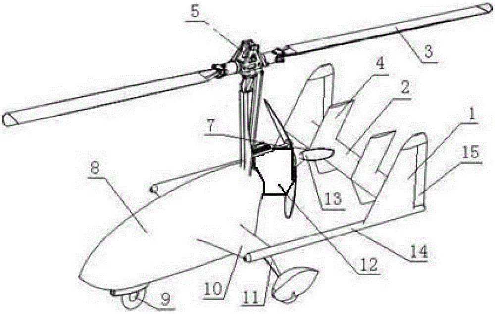
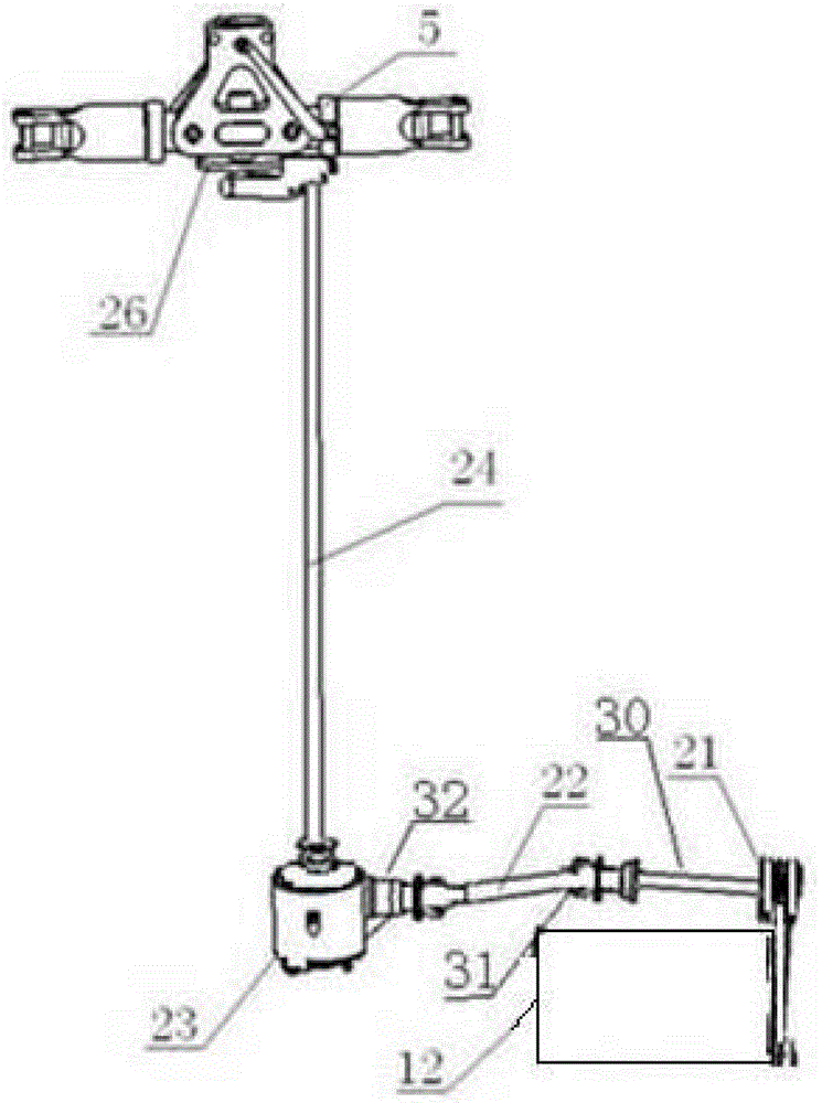
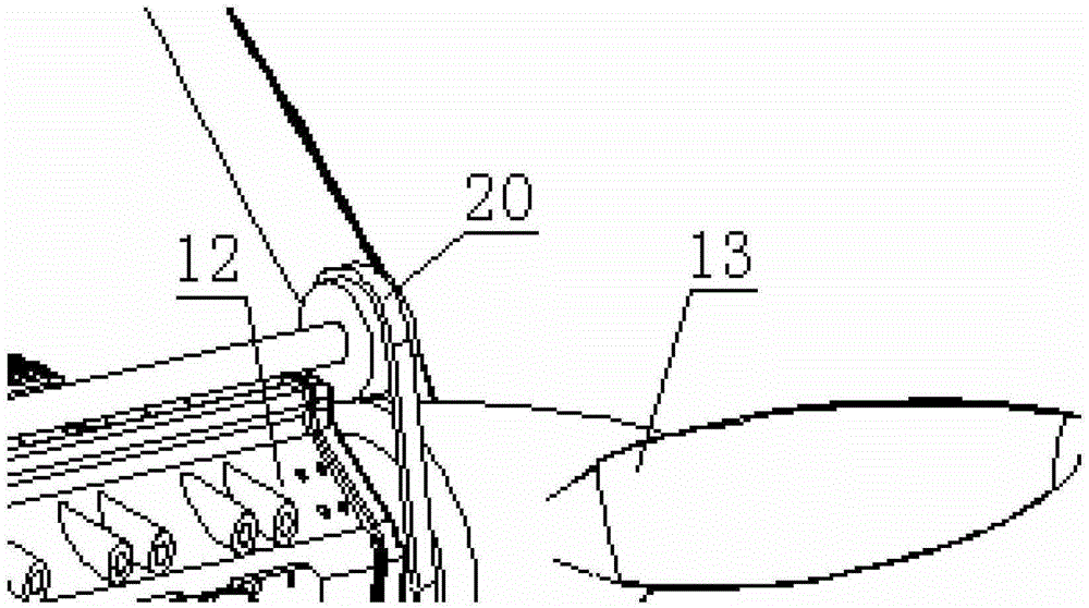
An STOL (short take off and landing) unmanned aerial vehicle with an unpowered-driven rotor wing comprises an aerial vehicle body, wings, a horizontal tail, vertical fins, an engine, a propeller, a rotor wing, a rotor wing prerotation device, undercarriages and a propeller hub, wherein the propeller is used for providing a thrust for flying forwards. When the unmanned aerial vehicle flies, airstream passes through a rotor wing disc from bottom to top to drive the rotor swing to rotate freely so as to generate a lift force; meanwhile, the rotor wing prerotation device is used for prerotating the rotor wing before takeoff; therefore, the short take off, even jumping take off, of the unmanned aerial vehicle can be realized. The STOL unmanned aerial vehicle with an unpowered-driven rotor wing has the advantages of high safety, low cost in the full service life, good flying performance and the like and has a bright application prospect.

Description

technical field [0001] The invention relates to the design of an unmanned aerial vehicle with a non-powered rotating wing, which belongs to the field of aviation vehicle design, especially the design field of unmanned aerial vehicles with short-distance take-off and landing requirements. Background technique [0002] A drone is a powered, unmanned, reusable or one-time-use aircraft. Existing UAV technology can be divided into fixed-wing UAVs and rotary-wing UAVs. [0003] Fixed-wing UAVs generally adopt horizontal taxi takeoff, hand throw takeoff, catapult takeoff, etc., and usually use taxi landing, parachuting and other landing forms. Hand-throwing and catapult take-off are limited by the strength of the personnel and the thrust of gunpowder and springs, which limits the weight of the task load and the weight of the fuel. The range is small, and it is not conducive to the full realization of the task. Parachute landing is not easy to accurately control the landing site, ...

Claims


Application Information

Patent Timeline
Patent Type & Authority Patents(China)
IPC IPC(8): B64C27/22
Inventor 魏凯马存旺李志国
Owner CHINA ACAD OF AEROSPACE AERODYNAMICS
Learn More