Four-speed power air and gas synchronous control valve

A synchronous control and air technology, applied in multi-port valves, valve devices, engine components, etc., can solve the problems of large randomness, heat loss, low energy utilization rate, etc., and achieve reasonable gas-to-air ratio and full and complete gas combustion. , the effect of improving the utilization rate of gas

Active Publication Date: 2013-11-20
YONGKANG HUAGANG KITCHENWARE
View PDF8 Cites 7 Cited by
  • Summary
  • Abstract
  • Description
  • Claims
  • Application Information

AI Technical Summary

Problems solved by technology

This method of operation has the following disadvantages: firstly, it is inconvenient to operate, has high requirements for the operator, is easy to misuse, and has serious safety hazards; It is difficult to accurately mix gas and air; if there is less air, the combustion of gas will not be sufficient, not only the energy utilization rate will be low, but also toxic and harmful gases such as CO will be produced, and the environment will be polluted; if there is too much air, the heat will be absorbed by the wind and lost. The gas is blown out of the combustion chamber by the wind without being completely burned, or even blows out the fire, which wastes energy and produces harmful gases such as CO, polluting the environment
It leads to poor combustion effect, low combustion efficiency, serious excessive CO and other harmful gases, and serious environmental pollution, which restricts the popularization and application of products
[0004] In response to the above problems, many manufacturers and people of insight have developed and developed, but so far no ideal products have come out.

Method used


Image

  • Four-speed power air and gas synchronous control valve
  • Four-speed power air and gas synchronous control valve
  • Four-speed power air and gas synchronous control valve

Examples


Embodiment Construction

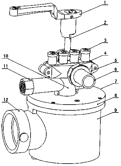
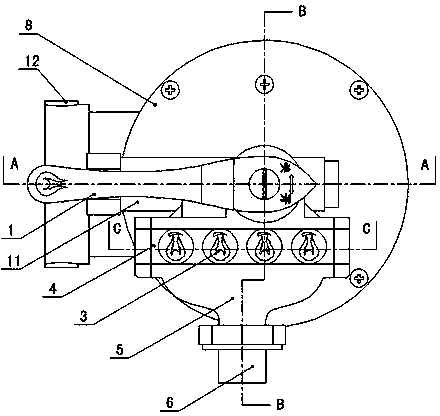
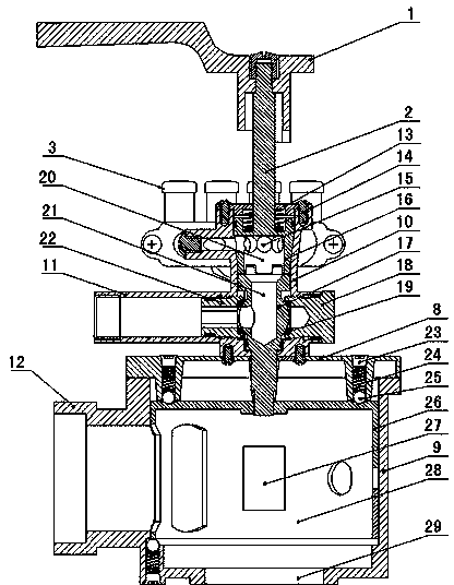
[0020] Figure 1 to Figure 5 Shown is a specific implementation of a four-stage power air synchronous control valve created by the present invention. It includes a handle 1, a valve stem 2, a gas valve, and an air valve 7. The air valve 7 is fixed on the gas valve. The valve includes a valve cover 13, an inlet valve core 16, an outlet valve core 17, and a valve body 10. The valve stem 2 is fixed to the inlet valve core 16, and the inlet valve core 16 and the outlet valve core 17 are arranged on the valve in a sealing manner. On the body 10, the intake valve core 16 is provided with an intake chamber 20, and the outlet valve core 17 is provided with an outlet chamber 21 communicating with the intake chamber 20, and the outlet chamber 21 corresponds to the outlet connector 11 on the valve body 10; The air valve 7 includes an air valve cover 8, an air valve core 26, and an air valve body 9. The air valve cover 8 is fixed on the air valve body 9, and the air valve core 26 is rotata...


PUM


Abstract

The invention discloses a four-speed power air and gas synchronous control valve comprising a handle (1), a valve rod (2), a gas valve and an air valve (7). The gas valve comprises a valve cover (13), an air inlet valve element (16), an air outlet valve element (17) and a valve body (10), wherein the air inlet valve element (16) and the air outlet valve element (17) are arranged on the valve body (10), the air inlet valve element (16) is provided with an air inlet cavity (20), the air outlet valve element (17) is provided with an air outlet cavity (21) communicated with the air inlet cavity (20), and the air outlet cavity (21) corresponds to an air outlet connector (11) on the valve body (10). The air valve (7) comprises an air valve cover (8), an air valve element (26) and an air valve body (9), wherein the valve rod of the air outlet valve element (17) extends into the air valve body (9) and is connected with the air valve element (26), and the valve rod (2), the air inlet valve element (16), the air outlet valve element (17) and the air valve element (26) can rotate synchronously. By means of the structure, the four-speed power air and gas synchronous control valve has the advantages of being simple in structure, convenient to operate, safe to use, accurate in gas and air ratio, high in energy utilization rate, little in environment pollution and the like.

Description

Technical field [0001] The invention relates to a control valve for a commercial gas cooker, in particular to an air-air synchronization control valve which can adjust the gas and air intake in proportion and can output four levels of power. Background technique [0002] In the cooking process of commercial gas stoves, the temperature rise speed is adjusted slower or faster according to the different regions, cuisines, and dishes. The ability to use the same air synchronous control valve to adjust the required power of each section between 8kw and 45kw does not exceed the normal combustion of CO. This is an industry problem and the highest level pursued by the industry. At present, most of the gas valves and air valves for controlling combustion of commercial gas stoves are operated separately. The air valve is first opened to blow air before ignition, the gas valve is opened, and the air intake volume of the air valve is adjusted. This type of operation has the following short...

Claims


Application Information

Patent Timeline
Patent Type & Authority Applications(China)
IPC IPC(8): F16K11/08
Inventor 施世佐
Owner YONGKANG HUAGANG KITCHENWARE
Why Eureka
Try Eureka