Air duct tightness test method
A test method and tightness technology, applied in the application of light to test fluid tightness, piping systems, mechanical equipment, etc., can solve problems such as rust marks on air ducts, and achieve accurate and reliable testing results
- Summary
- Abstract
- Description
- Claims
- Application Information
AI Technical Summary
Problems solved by technology
Method used
Image
Examples
Embodiment 1
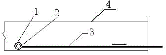
[0038] Such as figure 1 , 2 shown.
[0039] The air duct tightness testing method includes a light leakage detection method; the light leakage detection method includes the following steps:
[0040] Step 1. The step of building the light source: use the light bulb 2, the lampshade 1, and the wire 3 to build the light source, wrap the lampshade around the light bulb, and connect the wire to the light bulb;
[0041] Step 2. The step of establishing the light source in the air duct: place the light source established in step 1 in the air duct 4;
[0042] Step 3. Detection step: In a dark environment, drag the wire 3 so that the bulb 2 and the lampshade 1 move along the path of the air duct under the action of the wire 3, and observe whether there is light coming out of the air duct where the light source passes. If there is light coming out, it means that the air duct is leaking, if there is no light coming out, it means that the air duct is not leaking.
[0043]The dark envi...
Embodiment 2
[0045] Such as figure 1 , 2 shown.
[0046] The present embodiment also includes an air leakage detection method on the basis of Embodiment 1, and the air leakage detection method includes the following steps:
[0047] Step A, air duct sealing step: remove the branch pipe connected to the air duct, seal the opening of the removed branch pipe, seal the remaining ports of the air duct and maintain an air supply opening;
[0048] Step B, the installation step of the air supply device: take the centrifugal fan 5 and install it at the air supply opening of the air duct through the orifice plate 9;
[0049] Step C, the installation step of the detection tool: install the air flow differential pressure gauge 8 at the orifice plate 9, and install a pipe static pressure differential pressure gauge 11 in at least one position in the air duct;
[0050] Step D, detection step: start the centrifugal fan 5 to supply air to the inside of the air duct, so that the a...
Embodiment 3
[0058] Such as figure 1 , 2 shown.
[0059] This embodiment is on the basis of embodiment 1 or embodiment 2, because when the air leakage detection method shows that there is still a leak, because the air is colorless and odorless, the position of the leak cannot be intuitively shown. Use your hands to feel the leak point. Due to the large area of the air duct, there are many positions that need to be felt, so the leak point cannot be detected well. Therefore, in order to detect the leak hole conveniently and intuitively, it also includes smoke detection Leak detection method, smoke detection leak detection method comprises the steps:
[0060] Step a, air duct sealing step: remove the branch pipe connected to the air duct, seal the opening of the removed branch pipe, seal the remaining ports of the air duct and maintain an air supply opening;
[0061] Step b, the installation step of the air supply device: take the centrifugal fan 5 and install it at the air supply ...
PUM
 Abstract
Description
Claims
Application Information
 - R&D
- Intellectual Property
- Life Sciences
- Materials
- Tech Scout
- Unparalleled Data Quality
- Higher Quality Content
- 60% Fewer Hallucinations
Browse by: Latest US Patents, China's latest patents, Technical Efficacy Thesaurus, Application Domain, Technology Topic, Popular Technical Reports.
© 2025 PatSnap. All rights reserved.Legal|Privacy policy|Modern Slavery Act Transparency Statement|Sitemap|About US| Contact US: help@patsnap.com


