
A lag angle precision detection device capable of adjusting feeder height

A technology of a height adjustment device and a detection device, which is applied in the field of optical fiber precision winding, and can solve problems such as the inability to meet the requirements of optical fiber precision wiring.

Active Publication Date: 2015-09-16
CHANGCHUN EQUIP TECH RES INST
View PDF5 Cites 0 Cited by
  • Summary
  • Abstract
  • Description
  • Claims
  • Application Information

AI Technical Summary

Problems solved by technology

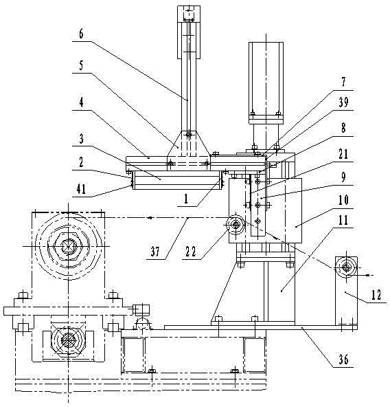
[0006] In order to overcome and make up for the lack of effective means and process devices for precise detection and control of the lag angle in the existing optical fiber precision wiring technology, and the technical deficiencies and defects that cannot meet the precision wiring requirements of the winding when the optical fiber is precisely and automatically wound, the present invention provides a A lag angle precision detection device capable of adjusting feeder height. It installs the industrial CCD camera and strip light source on the lifting plate of the feeder height adjustment device through the frame body assembly, and aligns the lens of the industrial CCD camera directly below. The moving optical fiber between the feeder wheel and the bobbin; when the number of fiber winding layers increases, the lifting plate will drive the fiber feeder wheel, industrial CCD camera and strip light source to rise simultaneously; by increasing the feeder height of the feeder wheel, the feeder wheel and The optical fiber between the bobbins is always kept horizontal, which improves the spatial accuracy of the lag angle measurement; and keeps the distance and angle of the industrial CCD camera and the bar light source for shooting and illuminating the fiber constant, ensuring the lag angle image The same shooting conditions greatly reduce the shooting error of the lag angle image, realize the precise detection of the lag angle in the process of precise wiring, and provide a powerful technical means for the realization of precise wiring

Method used


Image

  • A lag angle precision detection device capable of adjusting feeder height
  • A lag angle precision detection device capable of adjusting feeder height
  • A lag angle precision detection device capable of adjusting feeder height

Examples


Embodiment Construction

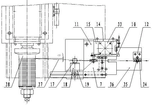
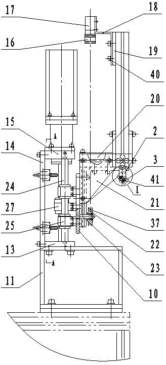
[0025] exist figure 1 , figure 2 , image 3 , Figure 4 and Figure 5 Among them, the specific embodiment of the present invention includes a delay angle precision detection device and a feeder height adjustment device, and the lag angle precision detection device is installed on the front of the lifting plate (10) of the feeder height adjustment device;

[0026] exist figure 1 , figure 2 , image 3 and Figure 5 Among them, the lag angle precision detection device includes a frame body, a lens (16), an industrial CCD camera (17), a bracket (18), an adjustment pad (19), two adjustment screws 1 (40), and a bar light source (3) , light source bracket 1 (1), light source bracket 2 (2), 4 adjusting screws 2 (41); the frame body includes aluminum profile 1 (9), aluminum profile 2 (20), aluminum profile 3 (4) , aluminum profiles 4 (6), inner connecting plate (21), outer connecting plate (39), upper connecting plate (7), lower connecting plate (8) and 2 T-shaped connecting ...


PUM


Abstract

The invention discloses a lag angle precision detection device capable of adjusting the height of a feeder line. The lag angle precision detection device can be used for precision detection of a lag angle in a precise automatic zero-defect winding process of an optical fiber, can avoid and eliminate winding defects of gaps, refolding and the like in an automatic wiring process of the optical fiber, and can meet precise wiring requirements in the automatic winding process of the optical fiber. According to the lag angle precision detection device, an industrial CCD (Charge Coupled Device) camera and a strip light source are mounted on a lifting plate of a height adjusting device of the feeder line by a frame body assembly; a lens of the industrial CCD camera is aligned to the moving optical fiber right below; when winding layers of the optical fiber are increased, the lifting plate drives a feeder line wheel, the industrial CCD camera and the strip light source to rise simultaneously, so that the optical fiber between the feeder line wheel and a winding tube is kept horizontal all the time; the measuring space precision of the lag angle is improved; shooting and illumination distances and shooting and illumination angles of the industrial CCD camera and the strip light source to the optical fiber are kept the same all the time; the identity of an image shooting condition of the lag angle is ensured; and the precision detection of the lag angle is achieved.

Description

technical field [0001] The invention belongs to the technical field of optical fiber precision winding, and relates to a lag angle precision detection device capable of adjusting feeder height, in particular, it can be used for precise detection of lag angle in the precise automatic defect-free winding process of optical fiber. Background technique [0002] With its unique material and excellent quality, optical fiber has been widely used in the field of national economy, especially in military affairs. Optical fiber guidance has broad application prospects, and optical fiber precision winding is an important technology in optical fiber guidance. Optical fiber precision winding is to precisely wind the optical fiber onto the bobbin layer by layer with a certain winding tension and a specified winding pattern without defects, and finally form a winding that meets the winding precision requirements. Precise wiring must be achieved when winding the winding, that is, the optica...

Claims


Application Information

Patent Timeline
Patent Type & Authority Patents(China)
IPC IPC(8): G01B11/26
Inventor 康战聂凤明吴庆堂修冬孙利忠段学俊李征陈洪海王凯尹英姿吴焕卢政宇魏巍郭波胡宝共李珊孙丽群张维杰孙洪宇王文渊
Owner CHANGCHUN EQUIP TECH RES INST
Learn More