Steel-concrete composite column anti-seismic anti-torsion test loading device and manufacturing method thereof

A technology of torsion test and loading device, which is applied in the direction of measuring device, using stable bending force to test the strength of materials, instruments, etc., can solve the problems of small stable loading stroke, single loading mode, lack of test data, etc., and achieve universality Strong, guaranteed free torsion, broad application prospects

Inactive Publication Date: 2013-11-20
TSINGHUA UNIV
View PDF7 Cites 37 Cited by
  • Summary
  • Abstract
  • Description
  • Claims
  • Application Information

AI Technical Summary

Problems solved by technology

However, the traditional torsion test loading device and test method have the following deficiencies: (1) The loading stroke is insufficient. Due to the better torsional ductility of the steel-concrete composite column, the torsion angle is larger at the limit state of the bearing capacity, so the test cannot be obtained. (2) The load mode is single, and only static torque and bending moment can be applied to the specimen alone, and the composite load of axial force, bending moment and torque with reciprocating characteristics cannot be applied; (3) Stable loading The stroke is small, a

Method used


Image

  • Steel-concrete composite column anti-seismic anti-torsion test loading device and manufacturing method thereof
  • Steel-concrete composite column anti-seismic anti-torsion test loading device and manufacturing method thereof
  • Steel-concrete composite column anti-seismic anti-torsion test loading device and manufacturing method thereof

Examples


Embodiment Construction

[0026] The structure, processing and use of the present invention will be further described below in conjunction with the accompanying drawings.

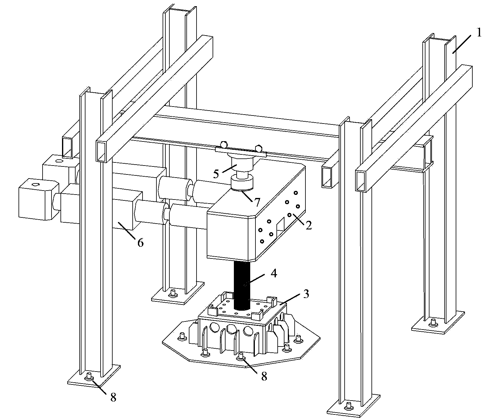
[0027] like figure 2 As shown, the device of the present invention includes a loading frame 1 , a top beam 2 , a base 3 , a test piece 4 , a thrust jack 5 , an electro-hydraulic servo actuator 6 , a friction-reducing plate 7 , and ground anchor bolts 8 . The structure of the top beam is as follows image 3 As shown, the base is constructed as Figure 4 As shown, the structure of the test piece is as follows Figure 5 shown.

[0028] The loading frame 1 is welded by steel plates, and each column foot of the loading frame is provided with a bolt hole 9, which is fixed to the ground through ground anchor bolts.

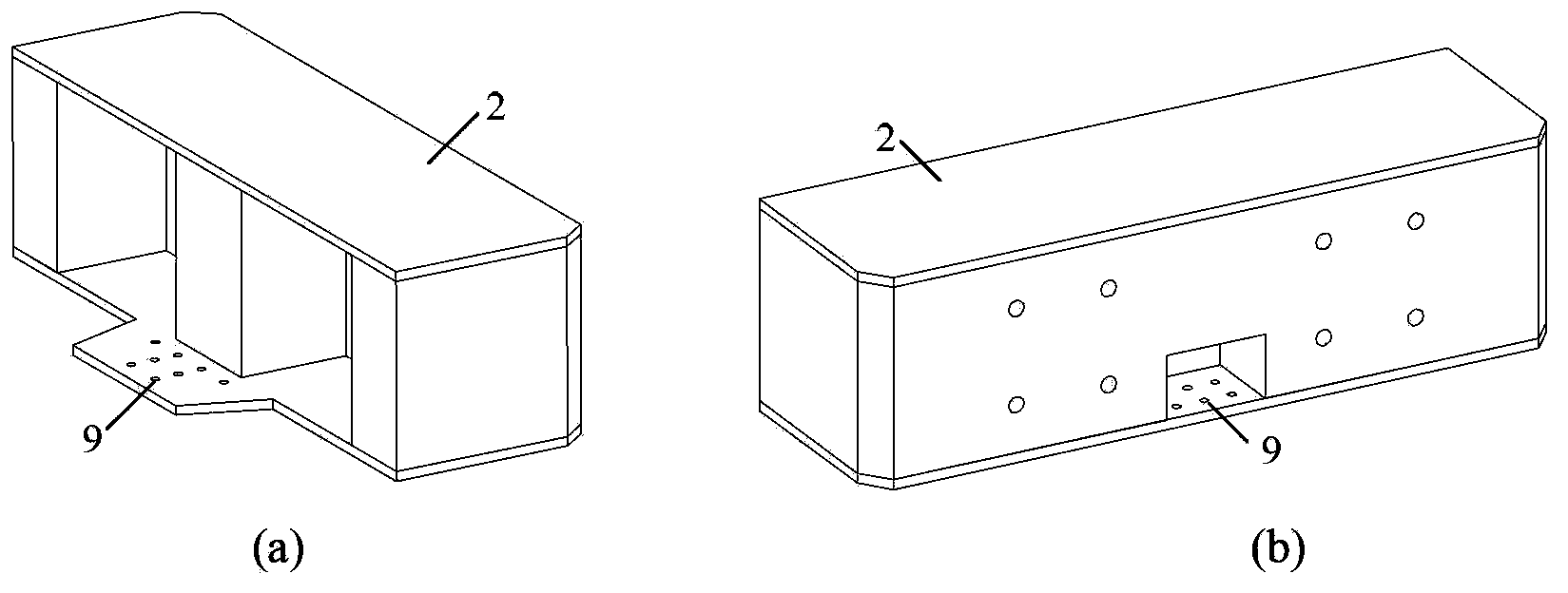
[0029] The top beam 2 is welded by steel plates, and the bottom of the top beam is provided with bolt holes 9, which are fixed to the top plate 11 of the test piece 4 through the bolts, so as to ensure the close connectio...


PUM


Abstract

The invention relates to a steel-concrete composite column anti-seismic anti-torsion test loading device and a manufacturing method thereof, and belongs to the technical field of structure engineering. The steel-concrete composite column anti-seismic anti-torsion test loading device comprises a loading frame, a top beam, a base, an antifriction plate, a thrust jack, and two electro-hydraulic servo actuators. The loading frame is obtained by welding steel plates. All column bases of the loading frame are provided with bolt holes and are fixedly connected to the ground by ground anchor bolts. The top beam is obtained by welding steel plates. The bottom of the top beam is provided with bolt holes and is fixedly connected to a top steel plate of a test piece by bolts. The base is obtained by welding steel plates. The top of the base is provided with bolt holes and is connected to a bottom steel plate of the test piece by bolts. An upper end of the thrust jack is connected to the loading frame by a rolling bearing. The antifriction plate is horizontally arranged in the center of the top of the top beam. The electro-hydraulic servo actuators are arranged horizontally and are fixedly connected to the top beam. The steel-concrete composite column anti-seismic anti-torsion test loading device solves the problem of the prior art, has a simple structure, is convenient for use, has strong universality, can be used for anti-seismic anti-torsion tests on various steel-concrete composite columns, and has wide application prospects.

Description

technical field [0001] The invention relates to a loading device for an aseismic and torsional test of a steel-concrete composite column, belonging to the technical field of structural engineering, in particular to the technical field of structural engineering testing. Background technique [0002] Steel-concrete composite columns have been widely used in engineering practice, and their main types include concrete-filled steel tube columns shown in Fig. la and figure 1 Steel reinforced concrete column shown in b. The torsional performance of steel-concrete composite columns is a matter of great concern in seismic design. Under the action of horizontal earthquakes in the longitudinal direction of the actual bridge structure, in addition to the axial force and bending moment, there are also torque effects in the pier columns. As a result, the piers of the bridge are in a state of combined axial force-bending moment-torque. Under the combined stress state, the pier column is ...

Claims


Application Information

Patent Timeline
IPC IPC(8): G01N3/26G01N3/20
Inventor 王宇航樊健生聂建国
Owner TSINGHUA UNIV
Why Eureka
Try Eureka