
Cooling and cleaning device for photoresist removing equipment

A cleaning device and equipment technology, applied in the direction of electrical components, semiconductor/solid-state device manufacturing, circuits, etc., can solve problems such as easy to fall, abnormal shape, easy to corrode, etc., and achieve the effect of ensuring safety

Inactive Publication Date: 2013-11-20
SHANGHAI HUALI MICROELECTRONICS CORP
View PDF4 Cites 2 Cited by
  • Summary
  • Abstract
  • Description
  • Claims
  • Application Information

AI Technical Summary

Problems solved by technology

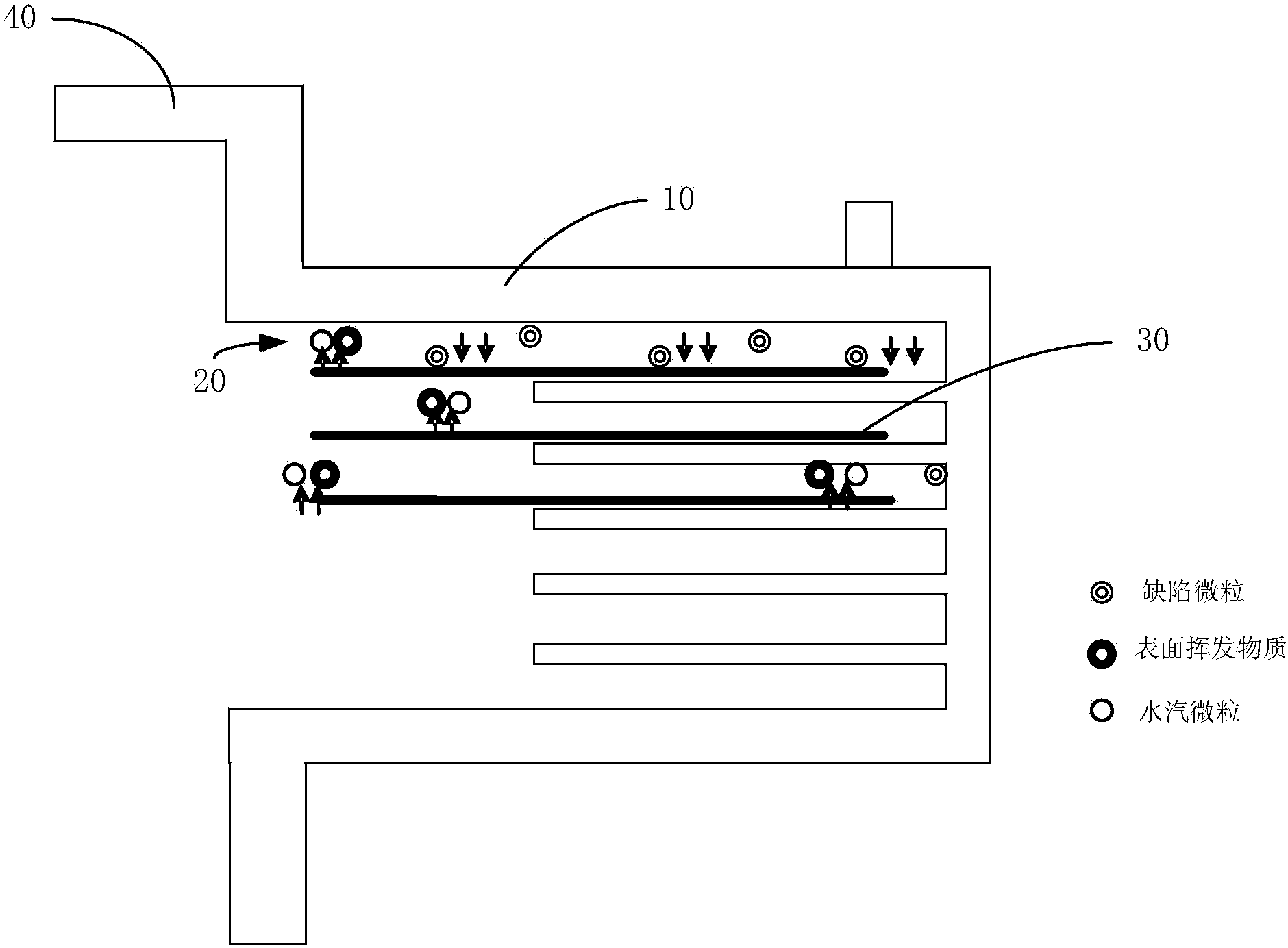
This condensate is most likely to be produced at the lowest temperature, that is, it gathers at the top of the cooling chamber 10, and the particles 20 (comprising water vapor particles, defect particles and wafer surface volatile substances) at the top of the cooling chamber 10 are easy to fall to the surface of the wafer 30. , forming defects, after particle defect scanning, it can be seen that a large number of tiny particles 20 are all over the surface of the wafer 30, and for the wafer 30 that still has a large amount of photoresist on the surface after treatment, the moisture contained in the particles 20 is very It is easy to corrode the photoresist on the surface of the wafer 30, resulting in abnormal appearance and adverse effects on production

Method used


Image

  • Cooling and cleaning device for photoresist removing equipment
  • Cooling and cleaning device for photoresist removing equipment

Examples


Embodiment Construction

[0014] In order to make the above objects, features and advantages of the present invention more comprehensible, specific implementations of the present invention will be described in detail below in conjunction with the accompanying drawings. It should be noted that all the drawings of the present invention are in simplified form and use inaccurate scales, and are only used to facilitate and clearly assist the purpose of illustrating the embodiments of the present invention.

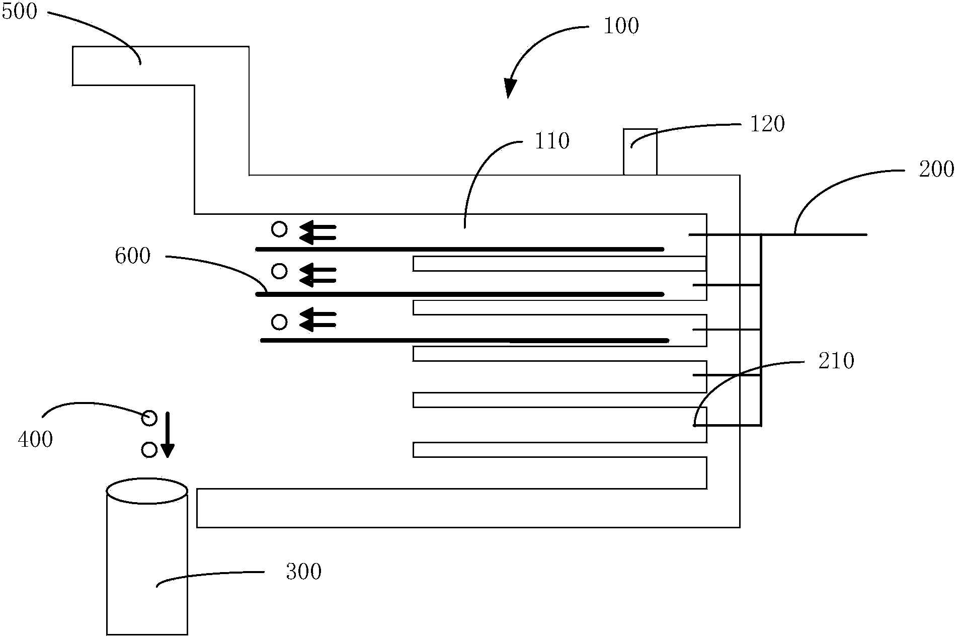
[0015] Please refer to figure 2 , the cooling and cleaning device of the degumming equipment provided by the present invention, comprising:

[0016] The cooling chamber 100 communicates with the atmospheric transmission chamber 500. The cooling chamber 100 is provided with multi-layer cavities 110, and the wafers 600 are respectively placed in the cavities 110 of each layer for cooling;

[0017] Purging device 200, one end of which is connected to an external air source, and the other end is provided ...


PUM


Abstract

The invention discloses a cooling and cleaning device for photoresist removing equipment, which comprises a cooling cavity, a sweeping device and an exhaust pipe, wherein the cooling cavity is communicated with an air transmission cavity, and a plurality layers of cavities are formed in the cooling cavity; one end of the sweeping device is connected with an external gas source, a plurality of blowing openings are formed in the other end of the sweeping device, and are dispersed in the plurality layers of cavities; the exhaust pipe is arranged at the bottom of the cooling cavity and at the downwind openings of the blowing openings. According to the cooling and cleaning device for the photoresist removing equipment, provided by the invention, water vapor inside the cooling cavity and volatile substances on the surfaces of wafers can be removed, so that tiny concretes are not generated inside the cooling cavity any more; further, other flaw particles inside the cooling cavity can be removed; the sweeping device arranged in the cooling and cleaning system can ensure that every wafer inside the cavity is cleaned up; the exhaust pipe additionally arranged below the outlet of the cooling cavity can discharge substances swept out, so as to ensure the safety of other wafers.

Description

technical field [0001] The invention relates to the field of integrated circuit manufacturing, in particular to a cooling and cleaning device for glue removal equipment. Background technique [0002] In plasma stripping equipment, a high temperature stripping process is used. Wafers need to be cooled after passing out of the high temperature process chamber. Current cooling devices such as figure 1 As shown, the wafer 30 enters the cooling chamber 10, which communicates with the atmospheric delivery chamber 40, and is cooled by factory circulating cooling water. Wherein, because the cooling water temperature of the factory is lower than that of the production workshop, the temperature at the surface of the wafer 30 is higher, and the temperature around the cooling chamber 10 is the lowest. A small amount of water vapor remains in the air in the cooling chamber 10, and the water vapor and trace volatiles on the surface of the high-temperature wafer 30 rise with the hot gas...

Claims


Application Information

Patent Timeline
Patent Type & Authority Applications(China)
IPC IPC(8): H01L21/67
Inventor 潘无忌张东海
Owner SHANGHAI HUALI MICROELECTRONICS CORP
Learn More