High-reliability LED (light emitting diode) bracket and LED device thereof

A technology for LED brackets and LED devices, applied in semiconductor devices, electrical components, circuits, etc., can solve the problems of water vapor or red ink setting effective obstacles, air tightness can not meet production requirements, reliability needs to be improved, etc., to achieve enhanced integration force, prolong the moisture penetration path, and improve the effect of air tightness

Active Publication Date: 2013-11-20
APT ELECTRONICS
View PDF8 Cites 8 Cited by
  • Summary
  • Abstract
  • Description
  • Claims
  • Application Information

AI Technical Summary

Problems solved by technology

[0004] However, due to the downward depression of the pits, no effective obstacles can be set for water vapor or red ink, and the airtightness still cannot meet the production requirements, and the plastic package 102 is thermoplastic, with poor heat resistance, and the reliability needs to be improved

Method used


Image

  • High-reliability LED (light emitting diode) bracket and LED device thereof
  • High-reliability LED (light emitting diode) bracket and LED device thereof
  • High-reliability LED (light emitting diode) bracket and LED device thereof

Examples


Embodiment 1

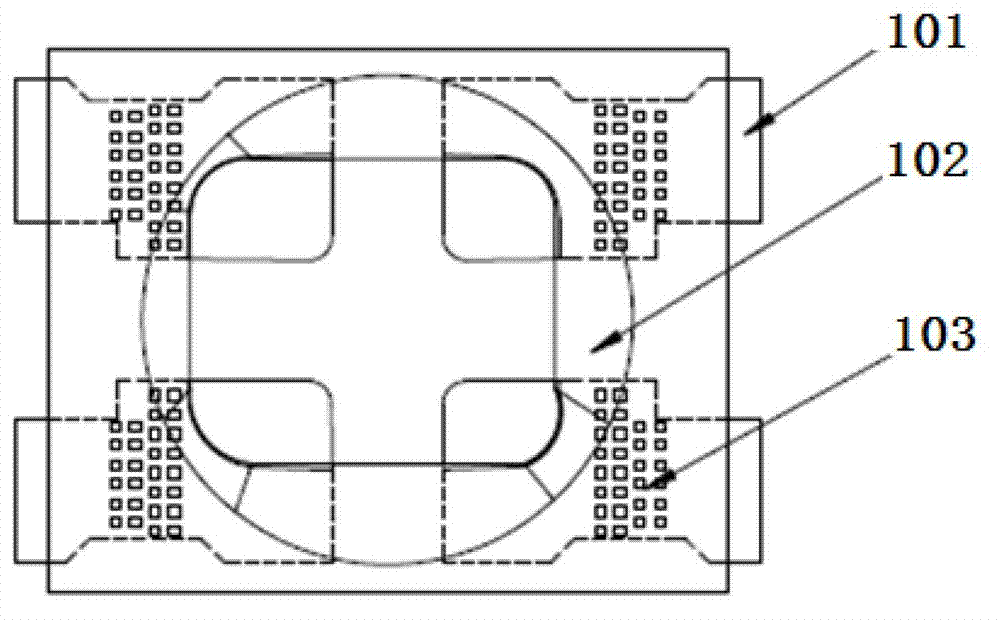
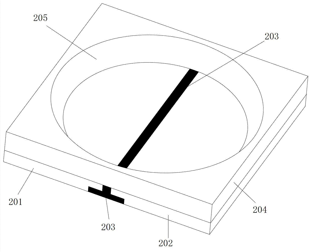
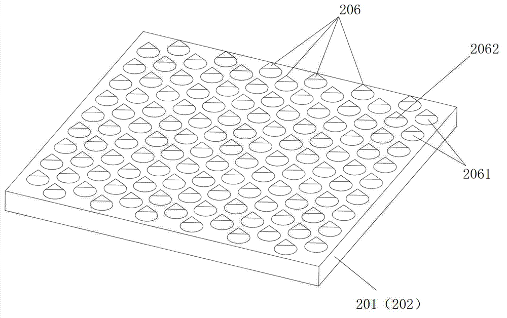
[0043] Such as figure 2 As shown, this embodiment discloses a high-reliability LED bracket, which includes a first pad 201 and a second pad 202 as conductive pins, and the first pad 201 and the second pad 202 pass through The insulating connecting colloid 203 is connected together, and an insulating seat 204 integrally formed with the connecting colloid 203 is also provided on the upper surface of the first pad 201 and the second pad 202, and an insulating seat 204 is formed inside the insulating seat 204. LED chips and reflective cups 205 for reflecting LED light are installed. Wherein, the first welding pad 201 and the second welding pad 202 are connected together through the connecting glue 203 integrally formed with the insulating seat 204, so that the firmness between the insulating seat 204 and the welding pads (201, 202) is strengthened. Not only that, in this embodiment, the unit protrusion structure 206 is provided on the upper surface of the first pad 201 and the s...

Embodiment 2

[0049] Such as Figure 4 As shown, the difference between this embodiment and Embodiment 1 is only that: the convex structure of the unit is changed from a conical shape to a prismatic shape. Compared with the conical structure, the prismatic structure makes the contact area between the two larger, so the bonding force is stronger. The path of moisture intrusion is further extended, and the reliability is better.

Embodiment 3

[0051] Such as Figure 5 As shown, the difference between this embodiment and Embodiment 1 is only that the raised structure of the unit is changed from a conical shape to a hemispherical shape. In this embodiment, the outer surface of the raised hemispherical structure presents a smooth curve shape, which greatly reduces the The stress on the bonding surface of 204 and the metal pad, under normal circumstances, the sharp corner is the stress concentration point, which is prone to the risk of microcracks and glue cracks caused by stress concentration, so the reliability of the bracket in this embodiment is better.


PUM


Abstract

The invention discloses a high-reliability LED (light emitting diode) bracket and an LED device thereof. The bracket comprises a first welding disc and a second welding disc, wherein the first welding disc and the second welding disc are used as conductive pins, the first welding disc and the second welding disc are connected together through an insulation connecting adhesive, the upper surfaces of the first welding disc and the second welding disc are provided with an insulation seat which is integrally formed with the connecting adhesive, the interior of the insulation seat is provided with a reflective cup for mounting an LED chip and reflecting the LED light rays, the upper surfaces of the first welding disc and the second welding disc, in contract with the insulation seat, are provided with a plurality of unit convex structures which are longitudinally and transversely staggered, and each unit convex structure of the back row is arranged relatively behind the gap between the two adjacent unit convex structures of the front row. The bracket and the LED device have the advantages that the firmness is further improved, the airtightness and the heat radiating performance are also improved, and the reliability is further improved.

Description

technical field [0001] The invention belongs to the technical field of LEDs, and in particular relates to a high-reliability LED bracket and an LED device thereof. Background technique [0002] As LED application fields become more and more extensive, the application side puts forward stricter requirements on LED reliability. How to manufacture a high-reliability LED bracket and its packaging device is extremely challenging. At present, the mainstream manufacturing method of the LED bracket is that the metal base is stamped to form the conductive pins and the crystal-bonding area of ​​the bracket, then electroplated, and the bracket insulating seat is made by injection molding technology, and finally the finished LED bracket is formed by bending. There is no bonding force between the plastic and the metal base of the bracket, so the airtightness is poor, water vapor penetrates into the LED chip through the joint interface gap, and the heat resistance of the plastic is poor, ...

Claims


Application Information

Patent Timeline
Patent Type & Authority Applications(China)
IPC IPC(8): H01L33/52H01L33/62H01L33/54H01L33/56H01L33/60H01L33/64
Inventor 何贵平陈海英许朝军孙家鑫肖国伟
Owner APT ELECTRONICS
Why Eureka
Try Eureka