
Capnography system for automatic diagnosis of patient condition

A CO2, patient technology, applied in diagnosis, diagnostic recording/measurement, application, etc., that can solve problems such as poor quality, fatigue, insufficient training and nursing staff

Active Publication Date: 2015-11-25
KONINKLJIJKE PHILIPS NV
View PDF3 Cites 0 Cited by
  • Summary
  • Abstract
  • Description
  • Claims
  • Application Information

AI Technical Summary

Problems solved by technology

Despite widespread use of CPR, its quality is often poor due to inadequate training and caregiver fatigue

Method used


Image

  • Capnography system for automatic diagnosis of patient condition
  • Capnography system for automatic diagnosis of patient condition
  • Capnography system for automatic diagnosis of patient condition

Examples


Embodiment Construction

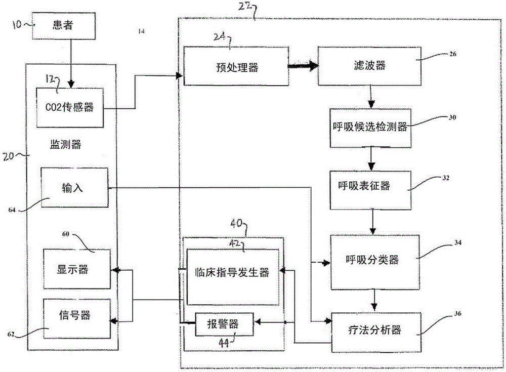
[0026] first reference figure 1 , a CO2 monitoring system 14 including a CO2 monitor 20 and a CO2 analyzer 22 is shown in block diagram form. A CO2 monitor was shown being used to monitor test patient 10. The CO2 monitor 20 is capable of monitoring CO2 and possibly other patient functions such as blood pressure, blood oxygen, ECG, and the like. The CO2 monitor 20 may also include controls, displays and indicator lights, as well as audible alarms and prompts.

[0027] The CO 2 sensor 12 in the CO 2 monitor 20 is provided with the patient's breathing gas. The CO2 sensor 12 senses the CO2 gas concentration in the exhaled breath of the subject. The CO2 measurement signal from the sensor 12 is delivered to a CO2 processor 22 . exist figure 1 In , the CO2 processor 22 is shown separate from the CO2 monitor 20 . However, the present invention is not limited thereto. The CO2 processor 22 may be in the monitor 20, may be a separate device, or may alternatively be constructed as ...


PUM


Abstract

An improved medical capnographysystem (22) automatically determines the effect of therapy on the underlying patient. The system enable the determination of proper endotracheal tube or advanced airway placement, the effectiveness of CPR, and the occurrence of the return of spontaneous circulation (ROSC) or loss of spontaneous circulation by use of a therapy analyzer (36) implementing an analyze therapy algorithm (336). The system may be implemented in platform-independent hardware or software.

Description

technical field [0001] The present invention relates to an improved medical carbon dioxide (CO2) monitoring system, and more particularly to a system for automatically determining the effectiveness of intubation or other advanced airway placement therapy or cardiopulmonary resuscitation (CPR) therapy or respiratory therapy applied to a patient CO2 monitoring system. Respiratory therapy may include monitoring responses to administration of bronchodilators for obstructive airway diseases such as asthma. The effectiveness of this therapy can be seen in the shape change of the CO2 waveform. The system also determines the occurrence of return of spontaneous circulation (ROSC) during treatment. Background technique [0002] CO2 monitoring systems are currently used in hospital operating rooms as well as in intensive care units to monitor a patient's breathing. Typically, these systems are large, complex ventilation systems that monitor the patient's oxygen intake and respirator...

Claims


Application Information

Patent Timeline
Patent Type & Authority Patents(China)
IPC IPC(8): A61B5/083A61M16/00
CPCA61B5/4848A61B5/0816A61B5/082A61B5/0826A61B5/0836A61M16/0051A61M16/04A61M2016/0413A61M2230/06A61M2230/205A61M2230/30A61M2230/432A61M16/021
Inventor S·巴巴埃萨德赫E·黑尔芬拜因D·巴特勒S·H·周
Owner KONINKLJIJKE PHILIPS NV
Learn More