Gunn diode oscillation signal source based on dielectric integrated waveguide resonant cavity, and working method thereof

A dielectric integrated waveguide and Gunn diode technology, applied in the direction of resonators, waveguide devices, electrical components, etc., can solve the problems of large packaging volume, inability to integrate, and demanding working environment, achieve high operating frequency, and avoid waste of resources , compact and lightweight effect

Pending Publication Date: 2022-02-08
SHANDONG UNIV +1
View PDF0 Cites 0 Cited by
  • Summary
  • Abstract
  • Description
  • Claims
  • Application Information

AI Technical Summary

Problems solved by technology

[0005] Traditional devices have the disadvantages of frequency limitation, strict requirements on the working environment, and obvious defects such as large packaging volume and inability to integrate, which limit the application in high frequency, integration and other fields

Method used


Image

  • Gunn diode oscillation signal source based on dielectric integrated waveguide resonant cavity, and working method thereof
  • Gunn diode oscillation signal source based on dielectric integrated waveguide resonant cavity, and working method thereof
  • Gunn diode oscillation signal source based on dielectric integrated waveguide resonant cavity, and working method thereof

Examples


Embodiment 1

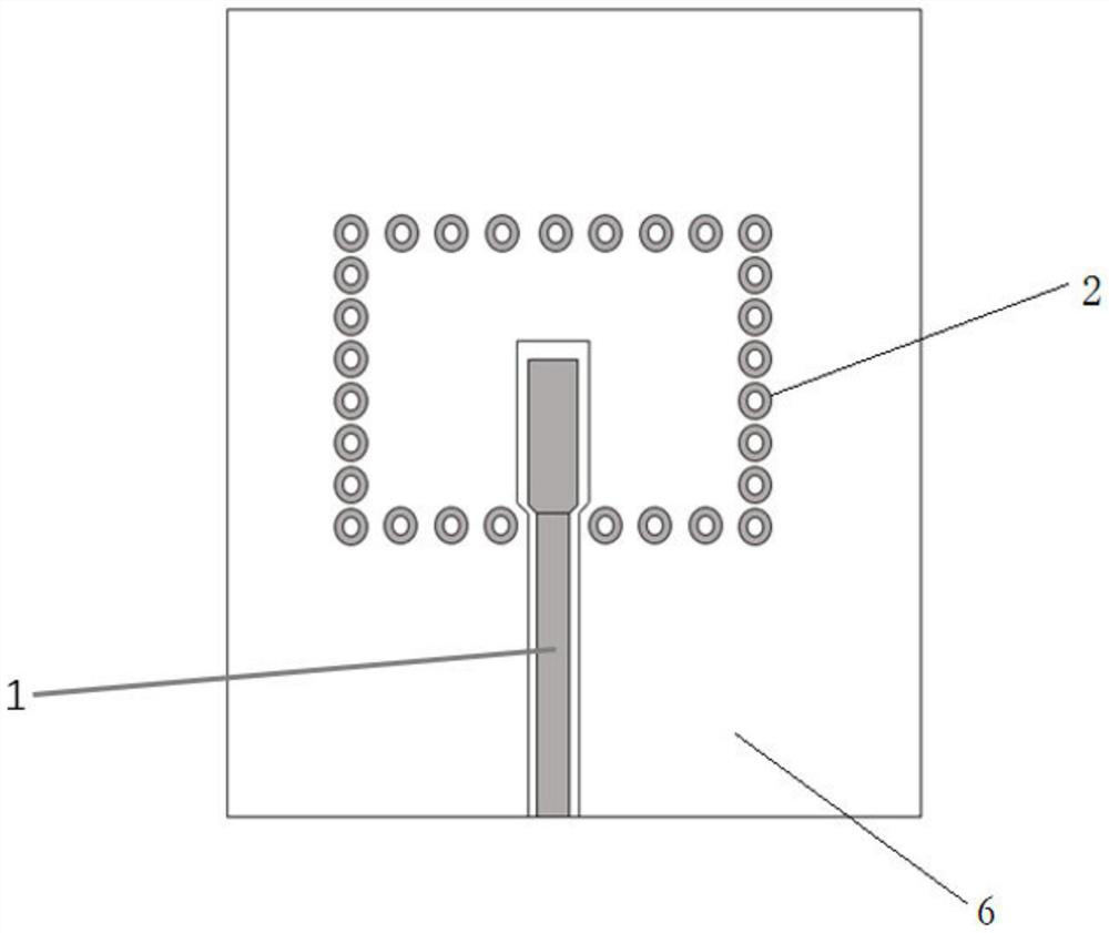
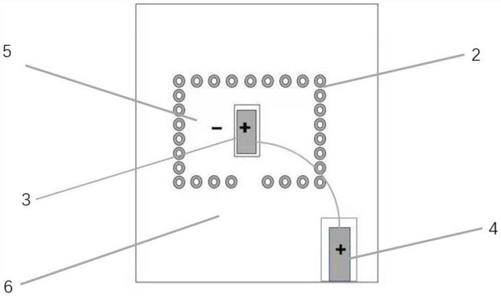
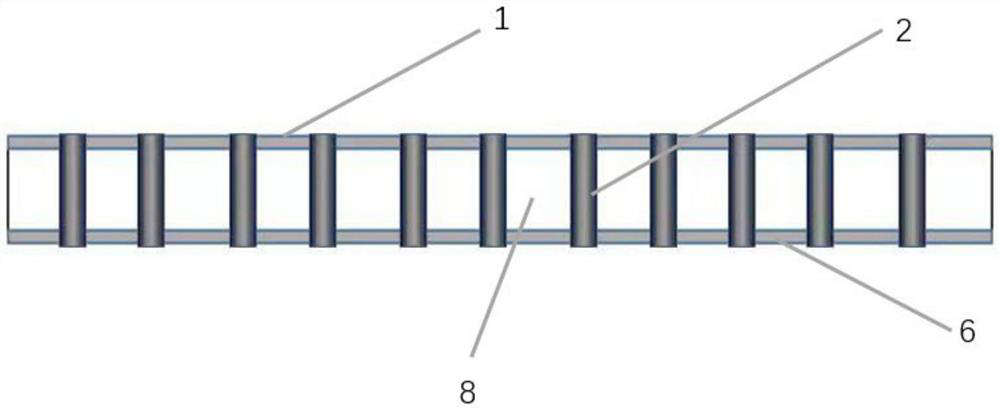
[0055] A Gunn diode oscillating signal source based on a dielectric integrated waveguide resonator, such as figure 1 , image 3 shown, including:

[0056] Top layer 1, middle layer 8 and bottom layer 6 from top to bottom; top layer 1 is a cpw (coplanar waveguide) multilayer metal structure, the middle layer 8 is an insulating sheet structure, and bottom layer 6 is a cpw (coplanar waveguide) multilayer metal structure ;

[0057] The via structure 2 that penetrates the top layer 1 , the middle layer 8 and the bottom layer 6 .

Embodiment 2

[0059] A Gunn diode oscillating signal source based on a dielectric-integrated waveguide resonator according to Embodiment 1, the difference is that:

[0060] CPW multi-layer metal structure and includes top-down 4-6um metal Au layer, 8-14um metal Ti layer, 8-12um metal Cu layer. The metal Au layer is to prevent oxidation and corrosion of the metal Cu layer, which affects the structural performance, and the metal Ti layer is to increase the adhesion of the Au layer and prevent falling off.

[0061] The middle layer 8 adopts Rogers sheet Rogers-4350B with a thickness of 4mil. It provides low dielectric constant and low loss, and its price is a fraction of traditional microwave materials, which saves production costs and improves the Q factor of the resonant cavity, but the selection of materials is not limited to this.

[0062] The via structure 2 is a structure that penetrates the top layer 1 , the middle layer 8 and the bottom layer 6 from top to bottom, and the via structur...

Embodiment 3

[0064] A Gunn diode oscillating signal source based on a dielectric-integrated waveguide resonator according to Embodiment 2, the difference is that:

[0065] The thickness of the metal Au layer is 5um, the thickness of the metal Ti layer is 12um, and the thickness of the metal Cu layer is 10um.

[0066] The diameter of the cylindrical hole is 100um.


PUM

PropertyMeasurementUnit
Thicknessaaaaaaaaaa
Thicknessaaaaaaaaaa
Thicknessaaaaaaaaaa

Abstract

The invention relates to a Gunn diode oscillation signal source based on a dielectric integrated waveguide resonant cavity, and a working method of the Gunn diode oscillation signal source. The Gunn diode oscillation signal source comprises: a top layer, a middle layer and a bottom layer from top to bottom. The top layer is of a coplanar waveguide multilayer metal feed and signal output structure, the middle layer is of an insulating plate structure, and the bottom layer is of a metal structure for Gunn diode integration; and the via hole structure penetrates through the top layer, the middle layer and the bottom layer. The invention has the advantages of stable output frequency, relatively simple structure, lower noise, small and exquisite appearance, light weight, easiness in circuit integration and higher cost effectiveness.

Description

technical field [0001] The invention discloses a Gunn diode oscillating signal source based on a dielectric integrated waveguide resonator and a working method thereof, belonging to the cross technical field of electromagnetic field and microwave technology and semiconductor technology Background technique [0002] In recent years, due to the research and development of some new technologies and new materials, terahertz technology has developed rapidly, and the research on terahertz wave radiation sources has also been paid attention to in the corresponding field, and set off a wave of upsurge. At present, the semiconductor solid-state signal sources used in the terahertz field are mainly negative resistance devices, such as Gunn Diodes (Gunn Diodes), Resonant Tunneling Diodes (RTDs), and IMPATT Diodes. Among these diodes, Gunn diodes have many advantages such as high operating frequency, strong stability, high reliability, low noise, wide frequency bandwidth, low power supp...

Claims


Application Information

Patent Timeline
IPC IPC(8): H01L47/02H01P7/06H01P11/00
CPCH01P7/065H01P11/008H10N80/107
Inventor 张翼飞孟令成王卿璞宋爱民王天露王萌发
Owner SHANDONG UNIV
Why Eureka
Try Eureka