Resonator silencer for a radial flow machine, in particular for a radial compressor

A technology of radial flow and compressor, which is applied to parts of pumping devices for elastic fluids, mechanical equipment, noise reduction devices, etc. It can solve problems such as the reduction of sound pressure peaks, and achieve the effects of reduced excitation and low pressure loss

Inactive Publication Date: 2013-11-20
SIEMENS AG
View PDF7 Cites 5 Cited by
  • Summary
  • Abstract
  • Description
  • Claims
  • Application Information

AI Technical Summary

Problems solved by technology

This results in a reduction of the sound pressure peaks at different frequencies in the interior of a chamber that is passed multiple times by the sound medium

Method used


Image

  • Resonator silencer for a radial flow machine, in particular for a radial compressor
  • Resonator silencer for a radial flow machine, in particular for a radial compressor
  • Resonator silencer for a radial flow machine, in particular for a radial compressor

Examples


Embodiment Construction

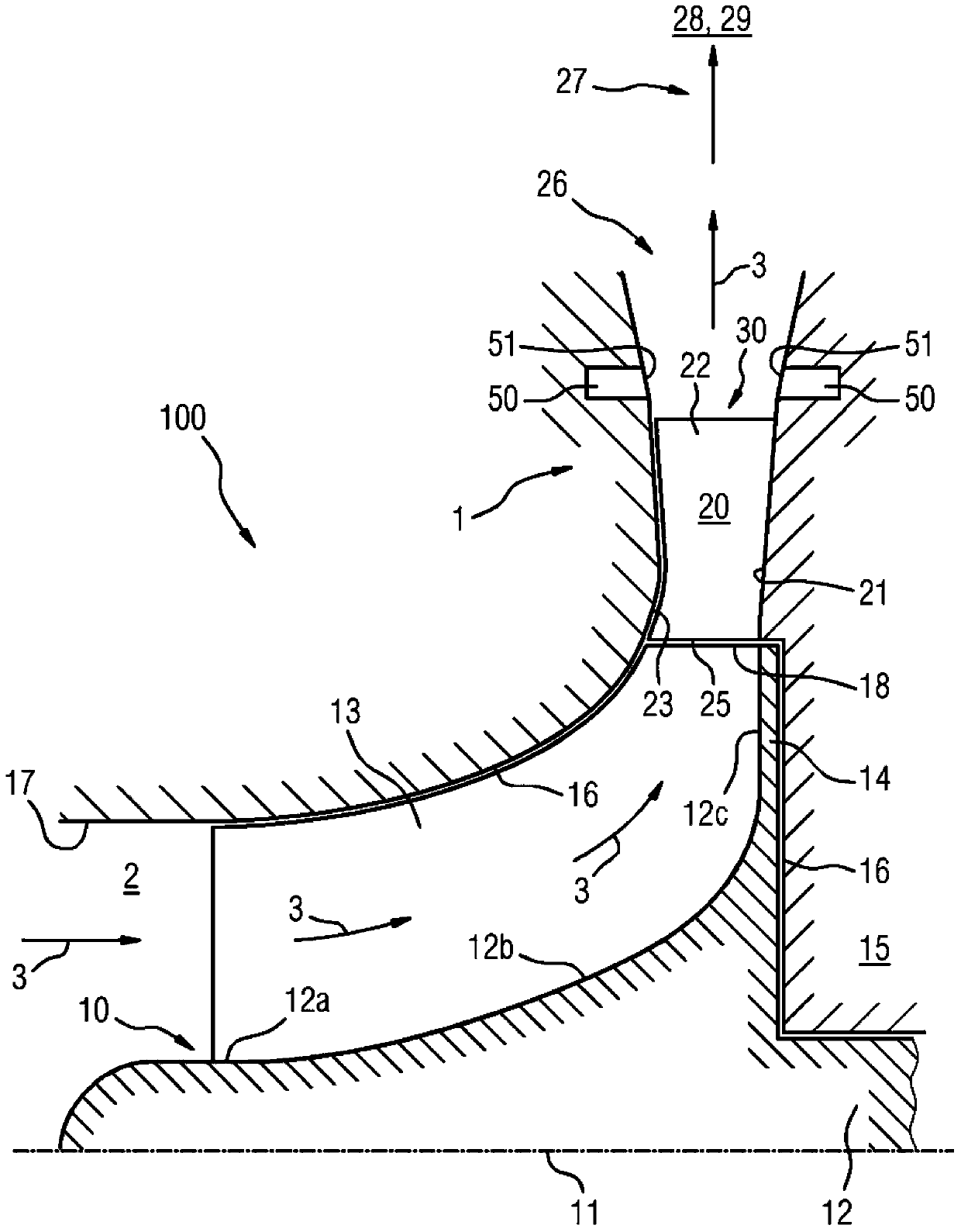
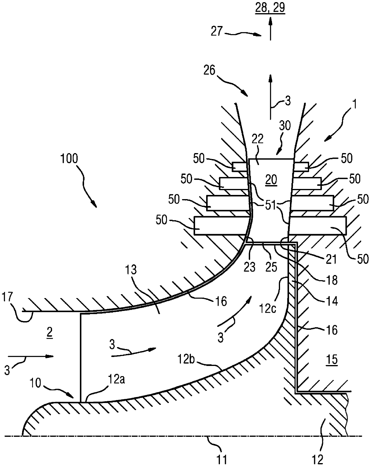
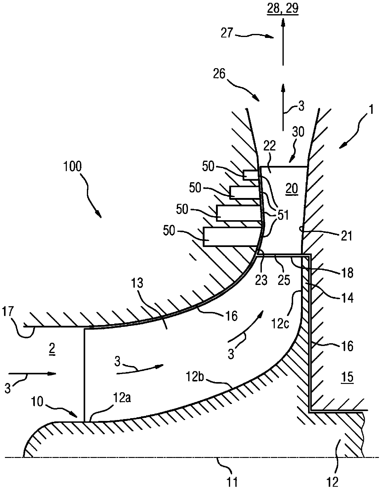
[0065] exist Figures 1 to 3 Different configurations of radial compressors 100 are described in , each with a resonator silencer 1 implemented in the diffuser or integrated in the diffuser.

[0066] Such a radial compressor 100 has, as shown, an impeller 10 which rotates at a high rotational speed about an axis 11 . The impeller 10 has a hub 12 and has blades 13 protruding radially from the hub.

[0067] The hub 12 has a first region 12a, which is substantially cylindrical; a transition region 12b, in which the radius of the hub increases; and an end region 12c, which is substantially perpendicular to the axis 11 Stretch.

[0068] —In Flow Direction 3 —Axially inflowing gas 2 rotates through impeller 10 and leaves impeller 10 in radial flow direction 3 relative to axis 11 and at an obtuse angle relative to axis 11 .

[0069] The blades 13 are fastened to a common back plate 14 of the hub 12 . The impeller 10 is located in a housing 15 whose walls 16 are adapted to the out...


PUM


Abstract

The invention relates to a volute (20) for a radial turbomachine, such as a radial compressor (100) or a radial turbine, in particular for a radial compressor (100) of this type. Said volute (20) has a substantially annular cavity (30) which is delimited at least by a first radial side surface (21, 23). According to the invention, at least one substantially annularly circumferential groove (50) is formed in said side surface (21, 23).

Description

technical field [0001] The invention relates to a diffuser for a radial fluid machine, in particular for a radial compressor. Background technique [0002] Radial compressors are known, for example, from EP 1 356 168 B1 or EP 1 602 810 A1. [0003] Such a radial compressor is formed by an impeller or vane wheel, which forms a compressor stage, rotates about an axis of rotation and has—relative to the axis of rotation of the impeller—an axial inlet and a radial outlet. The gas to be compressed flows axially into the impeller of the compressor stage and is then deflected outward (radially, radial direction), wherein it leaves the impeller at high speed. [0004] The kinetic energy of the gas leaving at high velocity and to be compressed is then converted in the diffuser into potential energy in the form of pressure. [0005] Such a diffuser is usually formed by two non-rotating rings forming an annular cavity or an annular chamber which adjoins radially on the impeller outle...

Claims


Application Information

Patent Timeline
Patent Type & Authority Applications(China)
IPC IPC(8): F04D29/42F04D29/44F04D29/66
CPCF01D9/02F04D29/4206F01N1/02F01D1/06F05D2260/96F04D29/665F04D29/444F05D2250/52
Inventor 斯文·柯尼希
Owner SIEMENS AG
Why Eureka
Try Eureka