Antenna adjusting method and device for multi-input and multi-output microwave system
A technology of microwave system and adjustment method, which is applied in the direction of transmission system, radio transmission system, diversity/multi-antenna system, etc., and can solve problems such as the inability to adjust antenna angles in multi-input and multi-output microwave systems
- Summary
- Abstract
- Description
- Claims
- Application Information
AI Technical Summary
Problems solved by technology
Method used
Image
Examples
Embodiment 1
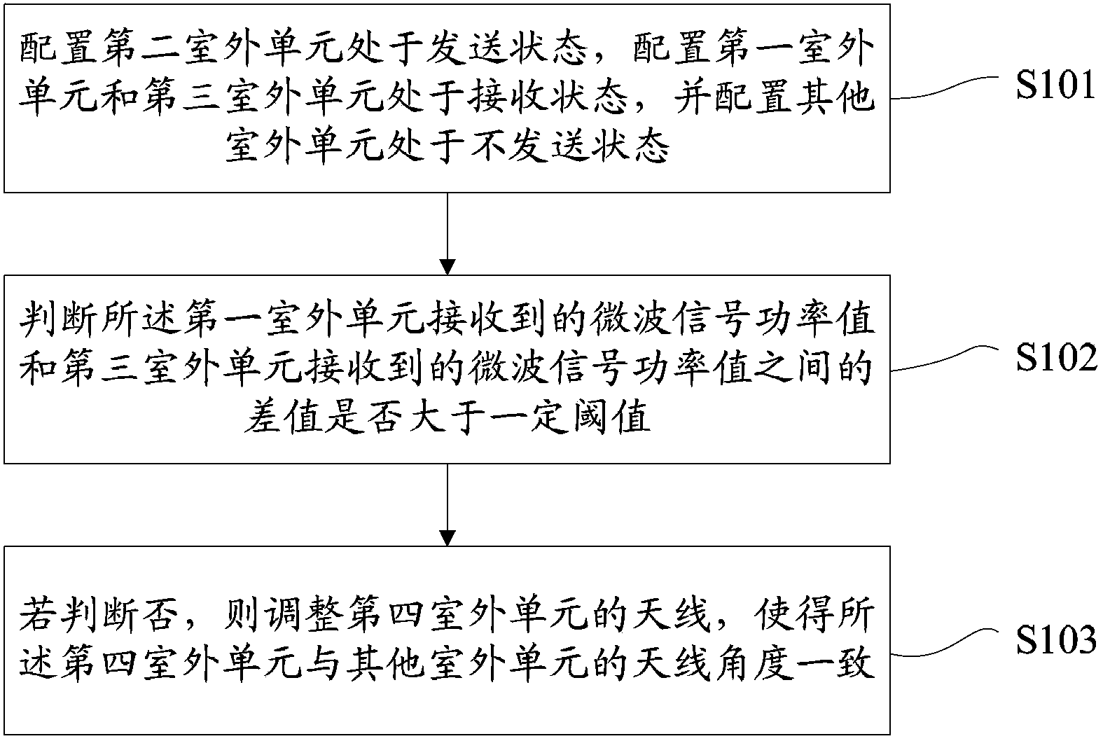
[0045] figure 1 A flow of an antenna adjustment method for a MIMO microwave system provided by the first embodiment of the present invention is shown, and only parts related to the embodiment of the present invention are shown for convenience of description.
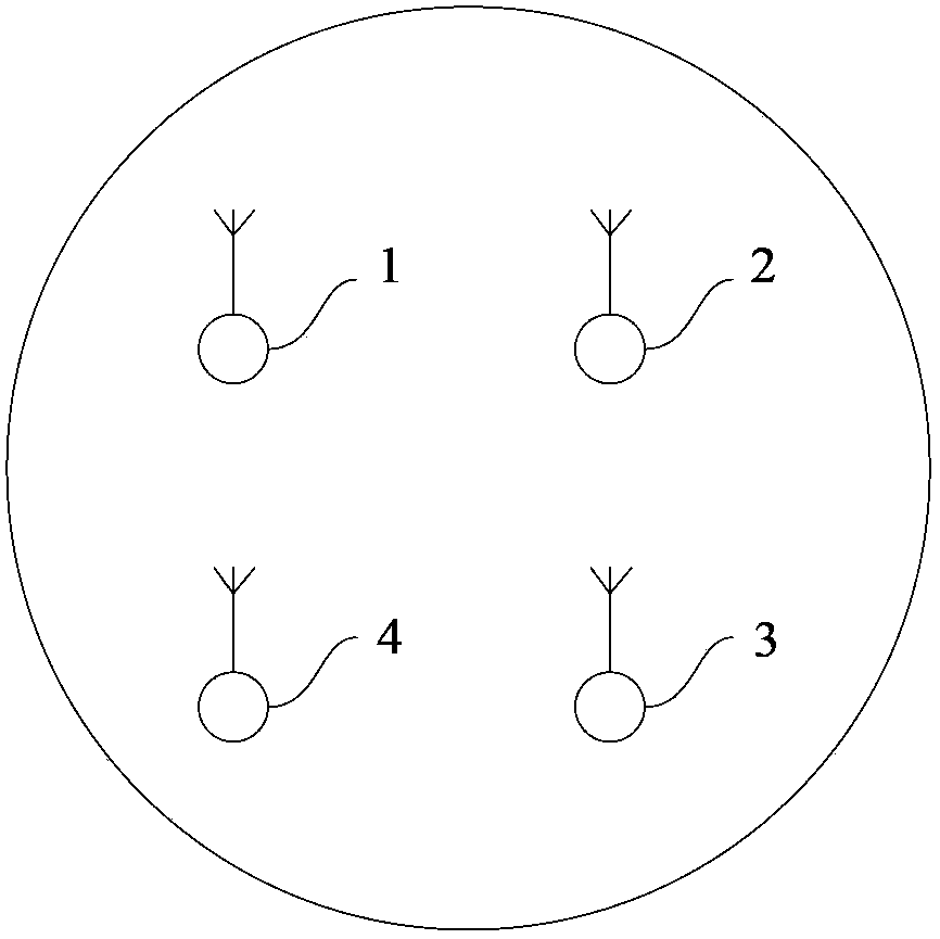
[0046] The antenna adjustment method of the MIMO microwave system provided by the implementation of the present invention is applied to the MIMO microwave system. The system includes four outdoor units, which are respectively the first unit to the fourth unit, and there is only one antenna of the outdoor unit. The antenna angles of the other three outdoor units are inconsistent, and the antenna adjustment method in this embodiment includes the following steps:
[0047] Step S101, configure the second outdoor unit to be in the transmitting state, configure the first outdoor unit and the third outdoor unit to be in the receiving state, and configure the other outdoor units to be in the non-transmitting state, wherein the a...
Embodiment 2
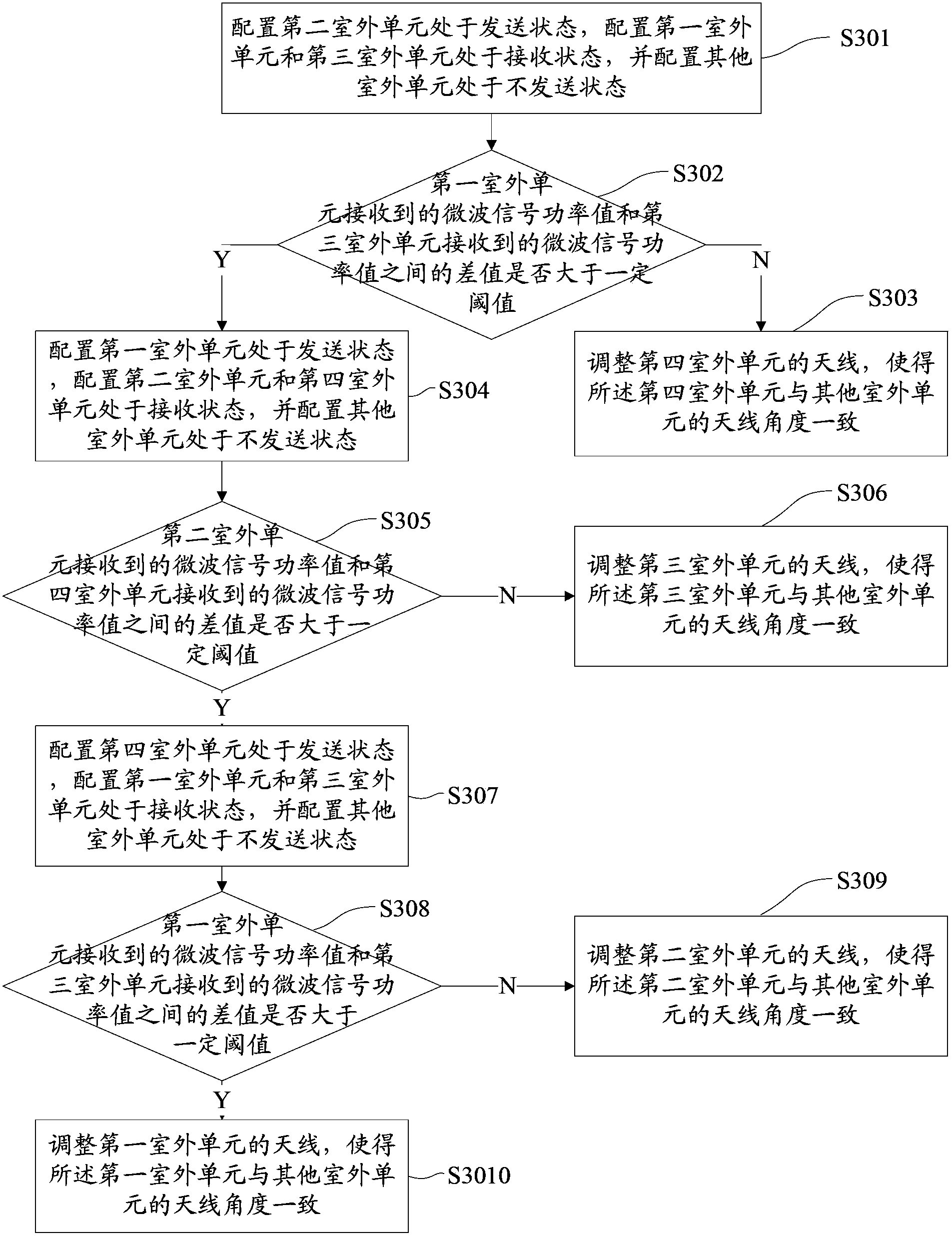
[0057] image 3 The flowchart of an antenna adjustment method for a MIMO microwave system provided by the second embodiment of the present invention is shown, and only the parts related to the embodiment of the present invention are shown for convenience of description.
[0058] Similarly, the implementation basis of this embodiment is that the MIMO microwave system includes four outdoor units, namely the first unit to the fourth unit, and the antenna angle of only one outdoor unit is inconsistent with the antenna angle of the other three outdoor units. The antenna adjustment method in the embodiment includes the following steps:
[0059] Step S301, configure the second outdoor unit to be in the transmitting state, configure the first outdoor unit and the third outdoor unit to be in the receiving state, and configure the other outdoor units to be in the non-transmitting state, wherein the antenna of the first outdoor unit and the antenna of the second outdoor unit The distanc...
Embodiment 3
[0087] Figure 4 A flow of an antenna adjustment method for a MIMO microwave system provided by the third embodiment of the present invention is shown, and only parts related to the embodiment of the present invention are shown for convenience of description.
[0088] The implementation basis of the antenna adjustment method for the MIMO microwave system provided in this embodiment is that the angles of the antennas of the two outdoor units in the MIMO microwave system already have the same angle and are in the correct angle direction, assuming that For the first outdoor unit and the second outdoor unit, the antenna adjustment method described in this embodiment includes:
[0089] Step S401, configure the second outdoor unit to be in the transmitting state, configure the first outdoor unit and the third outdoor unit to be in the receiving state, and configure the other outdoor units to be in the non-transmitting state, wherein the antenna of the first outdoor unit and the ante...
PUM
 Abstract
Description
Claims
Application Information
 - R&D
- Intellectual Property
- Life Sciences
- Materials
- Tech Scout
- Unparalleled Data Quality
- Higher Quality Content
- 60% Fewer Hallucinations
Browse by: Latest US Patents, China's latest patents, Technical Efficacy Thesaurus, Application Domain, Technology Topic, Popular Technical Reports.
© 2025 PatSnap. All rights reserved.Legal|Privacy policy|Modern Slavery Act Transparency Statement|Sitemap|About US| Contact US: help@patsnap.com


