Cervical vertebra examination chair
A cervical spine and shell technology, applied in the field of cervical spine detection chairs, can solve the problems of unsafety and low accuracy of cervical spondylosis, and achieve the effects of convenient operation, wide application range, and small space occupation
- Summary
- Abstract
- Description
- Claims
- Application Information
AI Technical Summary
Problems solved by technology
Method used
Image

Examples
Embodiment 1
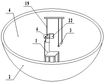
[0027] Embodiment one: combined with attached figure 1 , a cervical detection chair, comprising a detection chair 1, a housing 2, a head fixing device and an armrest 3, the housing 2 is provided with a hemispherical concave arc surface 4, and the detection chair 1 is arranged on the hemispherical concave arc of the housing 2 In the surface 4, at least three rollers are provided on the bottom surface of the testing chair 1, the head fixing device is arranged at the center of the shell 2, the height of the head fixing device can be adjusted, and the armrest 3 is arranged directly in front of the testing chair 1.
[0028] First install the shell on the ground, then install the rollers on the bottom of the test chair, then place the test chair in the hemispherical concave surface of the shell, the test chair will naturally roll to the bottom of the shell, and then fix the head The device is installed at the center of the shell, and finally the armrest is installed directly in fro...
Embodiment 2
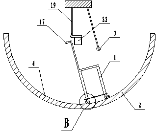
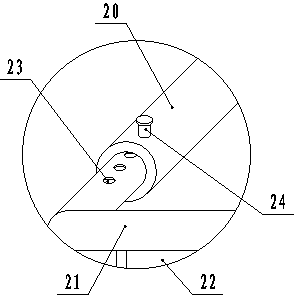
[0029] Embodiment two: combined with attached figure 1 , 2 , 3, 5, 6, 7, 9, a cervical detection chair, including a detection chair 1, a housing 2, a head fixing device and an armrest 3, the housing 2 is provided with a hemispherical concave arc surface 4, the detection chair 1 Set in the hemispherical concave arc surface 4 of the housing 2, the bottom surface of the detection chair 1 is provided with two rear directional wheels 5, two front directional wheels 6 and a front universal wheel 7, and the rear directional wheels 5 are respectively arranged on the detection The rear portion of the bottom surface of the chair 1, the front directional wheel 6 and the front universal wheel 7 are connected by a main shaft 8, the centerlines of the front directional wheel 6 and the front universal wheel 7 are perpendicular to each other, the main shaft 8 is provided with a bearing 9 and a rotary positioning device, The bearing 9 is connected with the bottom surface of the detection cha...
Embodiment 3
[0031] Embodiment three: combined with attached figure 1 , 2 , 4, 5, 8, 9, a cervical detection chair, including a detection chair 1, a housing 2, a head fixing device and an armrest 3, the housing 2 is provided with a hemispherical concave arc surface 4, and the detection chair 1 is arranged on In the hemispherical concave arc surface 4 of the housing 2, the bottom surface of the detection chair 1 is provided with a rear directional wheel 5, two front directional wheels 6 and a front universal wheel 7, and the rear directional wheels 5 are respectively arranged on the bottom surface of the detection chair 1. At the rear, the front directional wheel 6 and the front universal wheel 7 are connected through the main shaft 8, the centerlines of the front directional wheel 6 and the front universal wheel 7 are perpendicular to each other, the main shaft 8 is provided with a bearing 9 and a rotation positioning device, and the bearing 9 is connected to the detection The bottom sur...
PUM
 Abstract
Description
Claims
Application Information
 - R&D Engineer
- R&D Manager
- IP Professional
- Industry Leading Data Capabilities
- Powerful AI technology
- Patent DNA Extraction
Browse by: Latest US Patents, China's latest patents, Technical Efficacy Thesaurus, Application Domain, Technology Topic.
© 2024 PatSnap. All rights reserved.Legal|Privacy policy|Modern Slavery Act Transparency Statement|Sitemap