Shear flattening and cleaning device for cans

A technology for cleaning devices and cans, which is applied to the removal of solid waste, etc. It can solve the problems of machine jamming, feeding roller slippage, and difficulty in popularization, and achieve the effects of low machine failure rate, high conveying accuracy, and wide application range

Inactive Publication Date: 2015-08-12
史智勇
View PDF6 Cites 0 Cited by
  • Summary
  • Abstract
  • Description
  • Claims
  • Application Information

AI Technical Summary

Problems solved by technology

It has no cleaning function, cleaning can only rely on manual cleaning
The shearing and flattening machine with this structure enters between the active and passive feeding rollers along the shearing direction because the sheared cans transported by the conveyor belt enter between the active and passive feeding rollers, so the shrinking mouth cans are not easy to be involved by the active and passive feeding rollers Flatten between the two, so it is only suitable for shearing and pressing cans with the same outer diameter
In addition, the feed roller is prone to slipping, or even jamming. The jamming phenomenon is not easy to eliminate, and it is easy to cause secondary damage to the can body during feeding into the roller, which also makes it difficult to popularize.
(3) Chain conveying type can body shearing and flattening machine, its working method is: manually place the can body on the shear knife, the can body is cut along the axial direction and then sent to the triangular support plate by the conveyor chain, After being stretched by the triangular support plate, it tilts down to the side support plate of the roller by its own weight, and then repeats the working process of the support bar type can body shearing and flattening machine. The disadvantages of the support bar type pop can body shearing and flattening machine are They are also available, and are only suitable for cutting cans with compression openings; and because the driving chain is always rotating, the cans are easily damaged by the push plate on the chain when they are put in

Method used


Image

  • Shear flattening and cleaning device for cans
  • Shear flattening and cleaning device for cans
  • Shear flattening and cleaning device for cans

Examples


Embodiment Construction

[0025] The present invention will be further described below in conjunction with the accompanying drawings and specific embodiments.

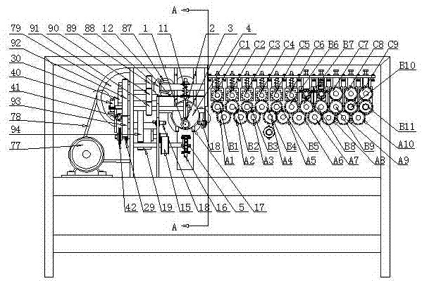
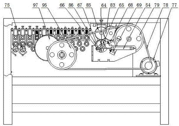
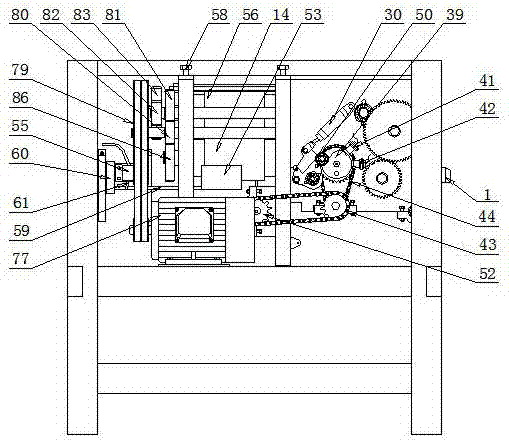
[0026] Such as figure 1 , figure 2 , image 3 , Figure 4 , Figure 5 , Figure 6 , Figure 7 , Figure 8 , Figure 9 , Figure 10 and Figure 11 As shown, this embodiment includes a frame, a shearing and conveying device, a feeding mechanism and a flattening device, a washing, squeezing and drying device, a transmission device and a control system.

[0027] The shearing and conveying device includes a feed shaft 1 fixed on the front end of the frame to match the tank body, an upper knife 2, a lower knife 3 fixed on the upper end of the feed shaft, a conical expansion shaft 4, a conveying chain 5, and a driving chain The operation control device of wheel 6, passive sprocket 7 and driving sprocket. The upper knife 2 is inlaid on the upper knife rest 8, and the upper knife rest 8 is fixed on the upper knife shaft 9, and the upper knif...


PUM


Abstract

The invention discloses a shearing, pressing and cleaning device of a pop-top can. The shearing, pressing and cleaning device comprises a frame, a shearing and conveying device, a feeding mechanism, a pressing device, a cleaning, wringing and drying device, a drive device and a control system, wherein the shearing and conveying device, the feeding mechanism and the pressing device are fixed on the frame; an upper knife and a lower knife of the shearing and conveying device are used for shearing a pop-top can body; a conveyor chain is used for directly conveying the can body to the feeding mechanism after the can body is expanded by a taper expanding shaft in the conveying process; the feeding mechanism is used for conveying the can body to an upper pressing roller and a lower pressing roller of the pressing device to press, then directly conveying to an upper cleaning brush roller and a lower cleaning brush roller on the cleaning device to clean, and then conveying into an upper wringing roller, a lower wringing roller, an upper drying roller and a lower drying roller to dry and send out. The shearing, pressing and cleaning device is high in conveying accuracy, stable in performance, high in reliability, convenient to operate, compact in structure, low in blockage fault rate, and wide in application range, does not damage the can body, and can be used for processing over 90% of pop-top can bodies in the market.

Description

technical field [0001] The invention relates to a recycling device for waste pop cans. Background technique [0002] Recycling of cans is an important strategy for the rational use of resources. It can not only effectively prevent the waste of cans from causing environmental pollution, but also re-use resources effectively and realize the secondary utilization of resources. How to effectively re-use cans is a need to solve a difficult problem. At present, I have invented a cutting machine for waste and old pop cans, which can automatically and quickly separate the body of waste and old pop cans from the lid and the bottom, saving labor. The next step is to axially cut the can body and flatten it for reuse. At present, there is also a device for axially cutting and flattening the can body on the market, but due to its various problems, it cannot be popularized and applied. At present, it mainly relies on manual cutting, resulting in waste of human resources and low producti...

Claims


Application Information

Patent Timeline
Patent Type & Authority Patents(China)
IPC IPC(8): B09B3/00B09B5/00
Inventor 史智勇魏俊萍
Owner 史智勇
Why Eureka
Try Eureka