
Combined femoral stem installer

A femoral stem and installer technology, which is applied in the femoral head, medical science, hip joint, etc., can solve the problems of difficult operation, increase the difficulty of operation, affect the field of operation, etc., to reduce the amount of removal, and the alignment process is convenient, accurate and convenient. effect of operation

Pending Publication Date: 2021-12-03
天衍医疗器材有限公司
View PDF6 Cites 0 Cited by
  • Summary
  • Abstract
  • Description
  • Claims
  • Application Information

AI Technical Summary

Problems solved by technology

[0003] 1. In the existing installation scheme, because the bolt needs to be screwed into the neck of the femoral stem by hand, the length of the bolt is longer. When the femoral stem and the bolt are placed in the hip joint, the bolt is likely to interfere with the greater trochanter. This makes the installation of the prosthesis trial model inconvenient, and for the smooth insertion of the bolts, a relatively large amount of large trochanter bone needs to be removed, which is not conducive to the operation process and postoperative recovery;
[0004] 2. After the femoral stem and bolts are placed into the hip joint, the bolts need to be loosened, and the puller acts on the bolts to adjust the angle of the femoral stem. However, in traditional structures, it is difficult for the puller to align the bolts, resulting in difficult operation. Moreover, the bolts are too long and are wrapped by the soft tissue of the large trochanter, which affects the surgical field of view and increases the difficulty of the operation.

Method used


Image

  • Combined femoral stem installer
  • Combined femoral stem installer
  • Combined femoral stem installer

Examples


Embodiment 1

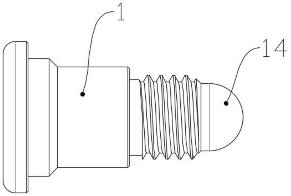
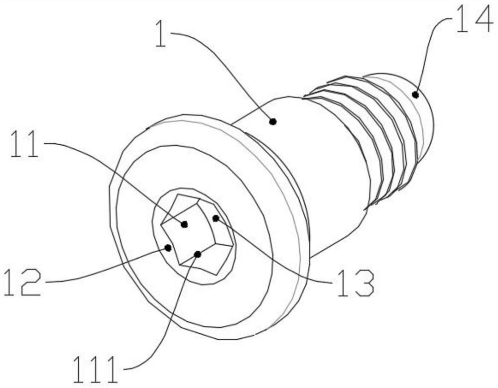
[0040] Embodiment 1: as Figure 1~6 , this embodiment provides the best solution for a combined femoral stem installer, including a bolt 1, a puller body 2 and a knob structure, wherein the bolt 1 is screwed to the neck of the femoral stem, when the femoral stem is placed At the hip joint, the puller body 2 can be applied to the bolt 1 to adjust the installation angle of the femoral stem. The knob structure is magnetic and is used to hold the bolt 1, which facilitates placing the bolt 1 on the femoral stem while preventing The bolt 1 is scattered before installation or falls during the operation, and because there is no need to manually hold the bolt 1, the length of the bolt 1 can be designed to be shorter, thereby reducing the amount of bone removal of the large trochanter during the operation , which is of great significance to the operation process and the follow-up recovery of patients;

[0041]Further, one end of the bolt 1 is provided with an inner corner hole 11, and ...

Embodiment 2

[0048] Embodiment 2: as Figure 7-10 , this embodiment provides the second scheme of the knob structure on the basis of the bolt 1 and the puller body 2 in Embodiment 1. Specifically, the knob structure is fixedly connected to the end of the puller body 2 away from the spherical angle 21 , so that the puller body 2 and the knob structure can be combined into one, thereby reducing the number of parts, avoiding complicated surgical tools, or avoiding loss of surgical tools;

[0049] Further, the knob structure includes a second knob body 41, a second cylinder 42 and an elastic body 43, wherein the second knob body 41 is located at the end of the puller body 2 away from the spherical angle 21, and is connected with the handle of the puller body 2. It is fixedly connected and becomes a part of the handle. The second knob body 41 is a hollow cylinder. The second cylinder 42 and the elastic body 43 are located in the second knob body 41. The elastic body 43 produces elastic force on...


PUM


Abstract

The invention discloses a combined femoral stem installer which is characterized by comprising a bolt, a striking and pulling device body and a knob structure, wherein the bolt is used for assisting in adjusting the installation angle of a femoral stem, and an inner angle hole is formed in one end of the bolt; the puller body acts on the bolt and is used for adjusting the installation angle of the femoral stem, and a spherical angle is arranged at one end of the puller body and corresponds to the inner angle hole; and the knob structure has magnetism and is used for holding the bolt. The alignment process between the bolt and the puller body is more convenient and accurate; when the femoral stem is adjusted, an acute angle can be formed between the puller body and the bolt, so that greater trochanter can be avoided, the thruster adapts to a narrow operation space, and an operator can operate conveniently; and the knob structure with magnetism is arranged, so that the bolt can be conveniently arranged on the femoral stem, and meanwhile, the bolt is prevented from scattering before installation or falling off in an operation.

Description

technical field [0001] The invention relates to the technical field of surgical instruments, in particular to a combined femoral stem installer. Background technique [0002] With the increasing aging of the world's population, senile degenerative bone and joint disease has become a common and frequently-occurring disease. After structural changes in the joints due to various reasons, the simple use of drug treatment can only partially relieve the pain symptoms, and it is difficult to improve the joint function. Artificial joint replacement can achieve the purpose of relieving pain, stabilizing joints, correcting deformity, and improving joint function. The femoral stem is a common prosthesis component for artificial hip replacement. The femoral stem prosthesis currently used is usually divided into combined type and There are two types of monolithic stems, among which the combined femoral stem has a wide range of market demands due to its various combinations and wide indi...

Claims


Application Information

Patent Timeline
Patent Type & Authority Applications(China)
IPC IPC(8): A61F2/46A61F2/38
CPCA61F2/4607A61F2/4601A61F2/3859A61F2002/4681
Inventor 周海利王楠
Owner 天衍医疗器材有限公司
Learn More