
Stamping feeding device for circular workpieces

A circular workpiece and semi-circular technology, applied in the field of feeding devices, can solve the problems of high manual labor intensity, low production efficiency, hand injury accidents, etc., to avoid industrial accidents, improve processing efficiency, and increase stamping yield Effect

Inactive Publication Date: 2013-11-27
吴江市钱氏纺织有限公司
View PDF0 Cites 23 Cited by
  • Summary
  • Abstract
  • Description
  • Claims
  • Application Information

AI Technical Summary

Problems solved by technology

Its disadvantages are: 1. Manual hand-held workpieces are prone to hand-injury accidents and cause work-related injuries when stamping.
2. The workpiece clamped by the clamp is not easy to accurately place on the lower die, resulting in defective stamping.
3. The production efficiency of stamping in this way is very low, and the labor intensity is high

Method used


Image

  • Stamping feeding device for circular workpieces

Examples


Embodiment

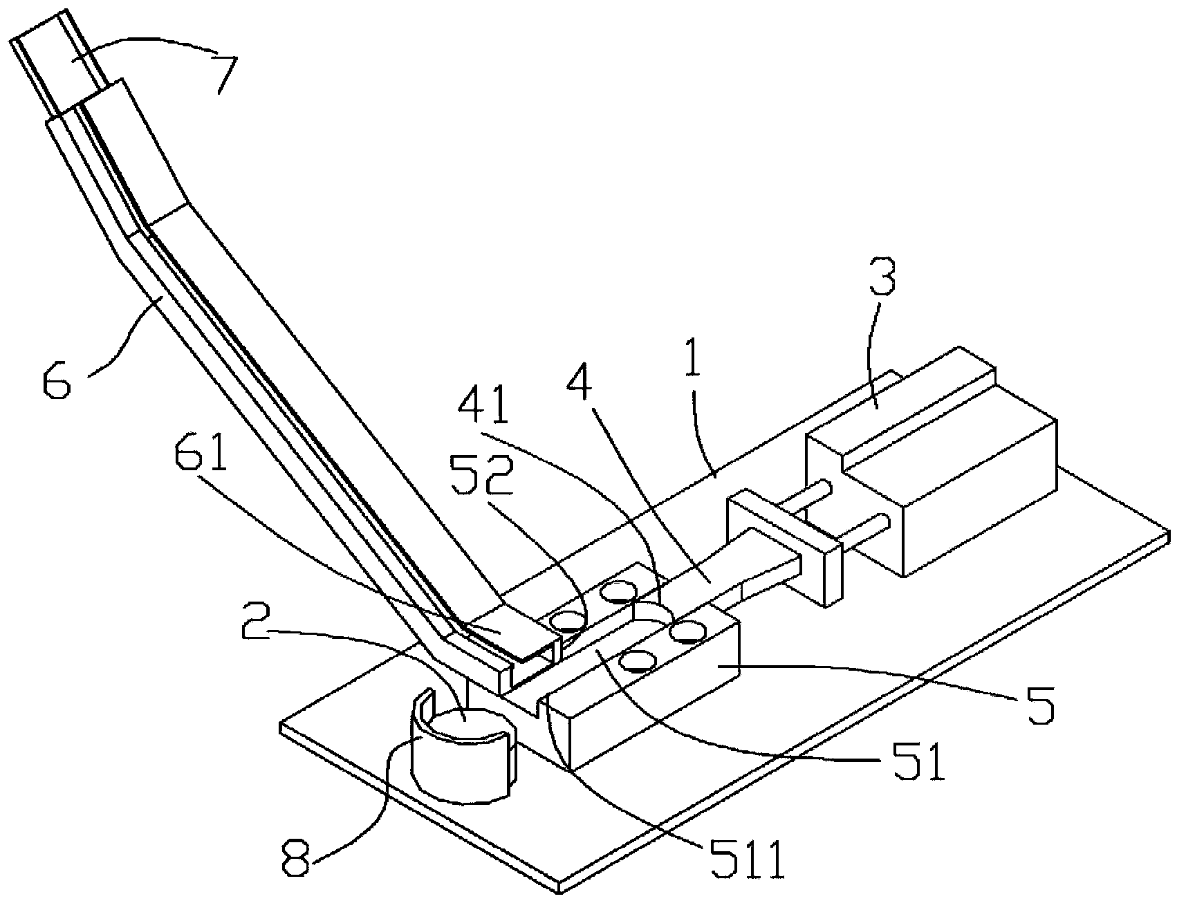
[0012] Example: see figure 1 As shown, the circular workpiece stamping and feeding device includes a punch table 1, on which a stamping lower die 2 is fixed, a push cylinder 3 is fixed on the punch table 1, and a push plate 4 is fixed on the push cylinder On the piston rod of 3, a through groove 51 and a gap 52 are formed on the square block 5, the outlet of the material channel 6 is connected with the through groove 51, and the push plate 4 is inserted and sleeved in the through groove 51;

[0013] The stamping lower die 2 is fixed with a semicircular baffle 8, the front end of the push plate 4 is formed with a semicircular jaw 41, and the upper surface of the stamping lower die 2 and the bottom surface of the through groove 51 are located on the same plane.

[0014] A feeding frame-shaped guide plate 7 is fixed on the forehearth 6 , the discharge section 61 of the forehearth 6 is parallel to the plane of the punch table 1 , and the discharge section 61 is fixed at the gap 52...


PUM


Abstract

A stamping feeding device for circular workpieces comprises a punch workbench (1); a stamping lower die (2) is fixed on the punch workbench (1); a workpiece pushing cylinder (3) is fixed on the punch workbench (1); an ejection plate (4) is fixed on a piston rod of the workpiece pushing cylinder (3); a through groove (51) and a notch (52) are formed in a square block (5); a discharge hole of a material channel (6) is connected with the through groove (51) in a communicating mode; the ejection plate (4) is inserted into the through groove (51) in a sleeve mode; a semicircular blocking piece (8) is fixed on the stamping lower die (2); a semicircular vice jaw (41) is formed at the front end of the ejection plate (4); the upper surface of the stamping lower die (2) and the bottom surface of the through groove (51) are in the same plane. The stamping feeding device for the circular workpieces has the advantages of improving the machining efficiency, avoiding industrial accidents and improving the rate of stamping finished products.

Description

Technical field: [0001] The invention relates to the technical field of stamping equipment, and more specifically relates to a feeding device used for stamping a disc-shaped workpiece on a stamping machine. Background technique: [0002] Existing stamping equipment, when processing disc-shaped workpieces, many factories use manual loading, hand-held or clamps to hold the workpiece and place it on the lower die of the punching machine, and then start the punching machine to let the upper die on the punch To stamp the workpiece. Its weak point is: 1, manual hand-held workpiece goes stamping and easily takes place to injure the hand accident, causes work-related injury. 2. It is not easy to accurately place the workpiece on the lower die with the clamps, resulting in defective stamping. 3. Carrying out stamping production efficiency is very low like this, and manual labor intensity is big. Invention content: [0003] The object of the present invention is to provide a punc...

Claims


Application Information

Patent Timeline
Patent Type & Authority Applications(China)
IPC IPC(8): B21D43/16B21D45/00B21D37/10B21D22/02
Inventor 钱树良
Owner 吴江市钱氏纺织有限公司
Learn More