
Screed and paver with same

A technology for screeds and pavers, applied in the directions of roads, road repairs, roads, etc., can solve the problems of uneven heating, deformation of the box bottom plate of the screed, affecting the quality of road paving, etc., so as to reduce thermal stress. Deformation, improving paving quality, reducing the effect of uneven heating

Active Publication Date: 2016-04-06
ZOOMLION HEAVY IND CO LTD
View PDF5 Cites 2 Cited by
  • Summary
  • Abstract
  • Description
  • Claims
  • Application Information

AI Technical Summary

Problems solved by technology

[0006] In the process of realizing the present invention, the inventor found that the above prior art has at least the following problems: the arrangement of the screed heating system in the screed of the prior art makes the heating degree of the bottom plate of the entire screed uneven, and due to the The uneven heating of the body base plate causes the box base plate of the screed to be easily deformed due to thermal stress, which affects the paving quality of the road surface

Method used


Image

  • Screed and paver with same
  • Screed and paver with same
  • Screed and paver with same

Examples


no. 1 example

[0042] Such as Figure 6 and Figure 7 As shown, the screed of the first embodiment shows the two middle sections of the screed and the screed heating system 600 . Each of the two intermediate panels includes a box body 200 , and the box body 200 includes a box bottom plate 100 . The screed heating system 600 includes a receiving cavity 610 and a heating device disposed in the box body 200 of each intermediate section.

[0043] In this embodiment, each plate section includes an accommodation cavity surrounded by a separate shell, in order to better heat the bottom plate 100 of the box body, as Figure 7 As shown, the bottom wall of the housing forming the accommodation cavity 610 abuts and fits with the upper surface of the box bottom plate 100 of the plate section where it is located. In an embodiment not shown, the bottom wall of the accommodation chamber may also be formed by the upper surface of the box bottom plate 100 of the plate section where the accommodation chamb...

no. 2 example

[0055] Such as Figure 8 and Figure 9 As shown, the screed of the second embodiment shows the two middle sections of the screed and the screed heating system 700 . Each of the two intermediate panels includes a box body 200 , and the box body 200 includes a box bottom plate 100 .

[0056] The screed heating system 700 includes an accommodating chamber 710 disposed in the box body 200 of each section, and includes a heating device, a circulation device, and a convection pipe 740 as a connecting pipeline.

[0057] In the second embodiment, each containing chamber 710 contains heat transfer oil as a heat transfer fluid.

[0058] The heating device of the second embodiment includes a heating box 720 and a box heater located outside each containing cavity and arranged on the circulation path of the heat transfer fluid. The setting method of this heating device enables the heat transfer fluid to be heated intensively, which can reduce the layout of cables in the electric heater ...


PUM


Abstract

The invention provides a screed and a paver comprising the same. The screed includes at least one plate section and a screed heating system, wherein the plate section comprises a box body and a box body base plate. The screed heating system consists of an accommodating chamber, a heating device and a circulation device, wherein the accommodating chamber is arranged inside the plate section box body and contacted with the box body base plate, and comprises thermal fluids used for heating the box body base plate; the heating device is used to heat the thermal fluids; the circulation device is connected through the accommodating chamber to drive the thermal fluids to cycle between the circulation device and the accommodating chamber. The screed in the invention speeds up the heat-transfer efficiency of the thermal fluids, thus enabling the box body base plate of the screed to be evenly heated, and also enhances the quality of the road paving by reducing the uneven heating degree and deformation induced by thermal stress of the body box base plate.

Description

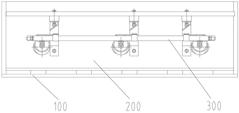
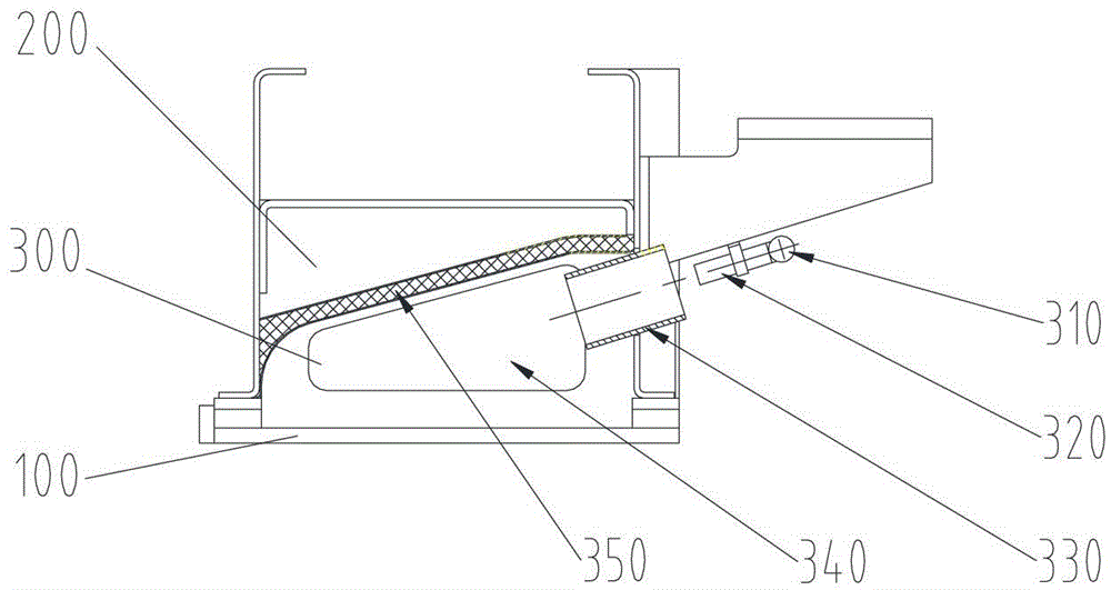
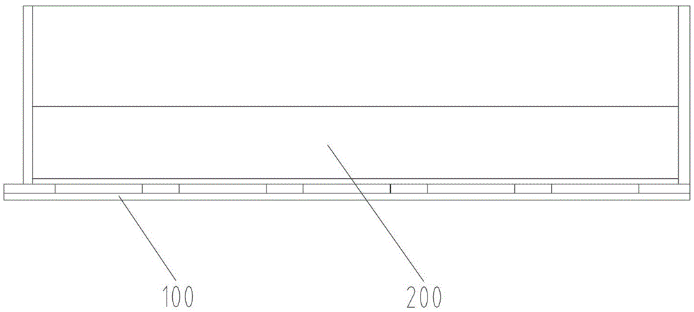
technical field [0001] The invention relates to the field of road construction machinery, more specifically, to a screed and a paver with the screed. Background technique [0002] Before or during the formal paving operation of the paver, the screed heating system should be used to heat the screed. Soften the asphalt condensed on the screed box bottom plate, tamper punch, scraper, etc., to facilitate the start of the tamper, and ensure the quality of the paved road surface, so as to ensure that the asphalt concrete does not cool down and condense during the starting stage of the paver. It does not affect the construction quality. In addition, the heated screed can also insulate the asphalt concrete during the paving process, preventing it from cooling down too quickly and reducing the paving quality. [0003] At present, there are two heating methods for paver screed: gas heating and electric heating. [0004] Figure 1 to Figure 2 A schematic structural view of an air-hea...

Claims


Application Information

Patent Timeline
Patent Type & Authority Patents(China)
IPC IPC(8): E01C19/48
Inventor 苏竹新刘兵华
Owner ZOOMLION HEAVY IND CO LTD
Learn More