Magnetic suction through combined floor drain

A combined, magnetic suction technology, used in waterway systems, indoor sanitary pipe installations, drainage structures, etc., can solve the problems of great influence of the downward moving distance of the sealing cover, slow drainage speed, and inability to reset, so as to ensure deodorization. Deodorizing effect, improving drainage speed, and increasing the effect of moving down

Active Publication Date: 2013-11-27
张小羊
View PDF6 Cites 8 Cited by
  • Summary
  • Abstract
  • Description
  • Claims
  • Application Information

AI Technical Summary

Problems solved by technology

[0004] In the above structure, due to the limitation of the installation space, the size of the two magnets cannot be made very large, which limits the suction force of the two magnets to a large extent, and the suction force becomes smaller and smaller as the sealing cover moves down. , in actual use, if the moving gap of the sealing cover is set too short, the sealing cover can be reset smoothly but the drainage speed is too slow; if the moving gap of the sealing cover is set too long, the suction force of the two magnets will be too small As a result, the sealing cover cannot be reset after draining, resulting in the failure of the anti-odor and anti-insect function of the floor drain, which brings great inconvenience to actual use
[0005] In addition, because the suction force of the two magnets is greatly affected by the downward movement distance of the sealing cover, when the sealing cover is at the lowest position during the drainage process, because the suction force of the two magnets is not enough, it can be reset only after the water is drained. At this time, the sealing cover and the floor drain The opening between the outlets under the main body is too large to be completely sealed by the drainage, and it is easy to cause the odor in the drainage pipe to rise and leak during the drainage process

Method used


Image

  • Magnetic suction through combined floor drain
  • Magnetic suction through combined floor drain
  • Magnetic suction through combined floor drain

Examples


Embodiment approach

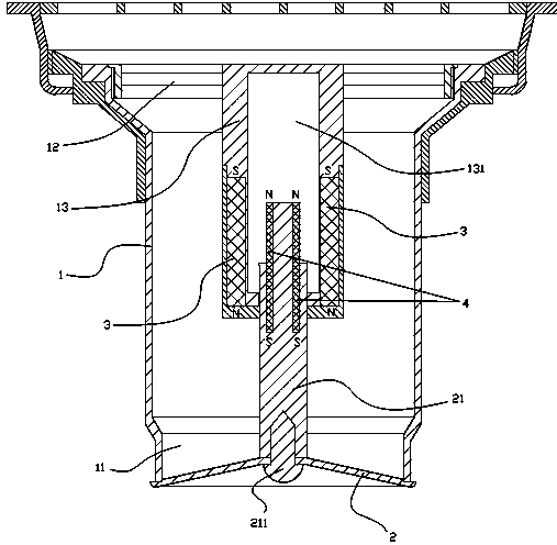
[0053] like Figure 14-15 As shown, it is the seventh embodiment of the present invention, the magnetic poles of the outer magnetic strip 3 are distributed on both sides inside and outside, and the magnetic poles of the inner magnetic strip 4 are also distributed on the two side walls, and the outer magnetic poles of the inner magnetic strip 4 and the corresponding positions The magnetic poles at the inner ends of the outer magnetic strips 3 are the same. In the figure, the left magnetic pole of the inner magnetic strip 4 is N and the right magnetic pole is S, the inner magnetic pole of the corresponding left outer magnetic strip 3 is N, and the inner magnetic pole of the right outer magnetic strip 3 is S.

[0054] When not draining water, the inner magnetic strip 4 is located at the middle and upper part of the outer magnetic strip 3 under the same and repulsive effect as the inner magnetic pole of the corresponding side outer magnetic strip 3 . When draining water, the seal...


PUM


Abstract

The invention discloses a magnetic suction through combined floor drain comprising a floor drain body and a seal cover which is arranged at the lower outlet of the floor drain body, is provided with a guide rod and is capable of moving up and down; an installation column is arranged in the middle of the floor drain body through a plurality of connecting strips; an installation hole is arranged in the installation column; at least one outer magnetic strip is arranged on the wall of the installation hole, and all the outer magnetic strips are distributed in a circumference relative to the center of the installation center; the tail end of the guide rod of the seal cover extends into the installation hole; at least one inner magnetic strip is arranged on the tail end of the guide rod; all the inner magnetic strips are pushed upwards by the outer magnetic strips and have the tendency of moving upwards, so that the seal cover on the guide rod seals the lower outlet of the floor drain body. The magnetic suction through combined floor drain has the characteristics that the sealing performance is good, the draining speed is high, and sludge and other impurities are not easily deposited, and can effectively prevent the seal cover from resetting and losing effect.

Description

technical field [0001] The invention relates to a floor drain, in particular to a magnetic suction straight-through combined floor drain. Background technique [0002] The floor drain is an important interface connecting the drainage pipeline system with the indoor floor. The floor drain has the functions of drainage, preventing the odor in the drainage pipeline from being transmitted back to the room, anti-clogging, and easy cleaning. [0003] The existing magnetic suction straight-through floor drain includes a floor drain body, a floor drain cover arranged on the upper opening of the floor drain body, and an installation sealing cover arranged at the outlet of the floor drain body. The top of the guide rod of the floor drain body and the sealing cover is each provided with a magnet The two magnets are arranged opposite to each other with different poles. In the initial state, the sealing cover is tightly attached to the lower outlet of the floor drain body and sealed by r...

Claims


Application Information

Patent Timeline
Patent Type & Authority Applications(China)
IPC IPC(8): E03F5/04E03F5/042E03F7/06E03C1/298
Inventor 张小羊
Owner 张小羊
Why Eureka
Try Eureka