Jointing structure of composite floor

A technology for superimposing floor slabs and structures, applied in the direction of floors, building structures, building components, etc., can solve problems such as cracks at the joints and changes in the mechanical performance of the slabs, so as to save the formwork process and ensure the mechanical performance , the effect of shortening the construction period

Inactive Publication Date: 2013-11-27
NANJING UNIV OF TECH
View PDF3 Cites 11 Cited by
  • Summary
  • Abstract
  • Description
  • Claims
  • Application Information

AI Technical Summary

Problems solved by technology

However, unreasonable splitting methods and splicing structures will lead to changes in the mechanical properties of the plates, and cracks are prone to appear at the splicing

Method used


Image

  • Jointing structure of composite floor
  • Jointing structure of composite floor
  • Jointing structure of composite floor

Examples


Embodiment 1

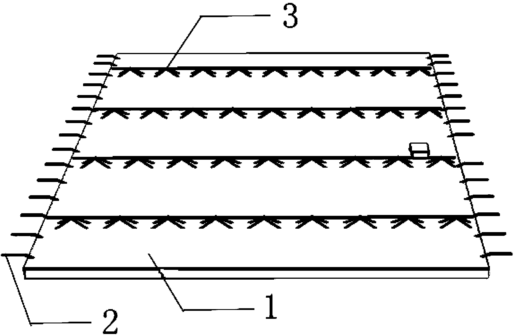
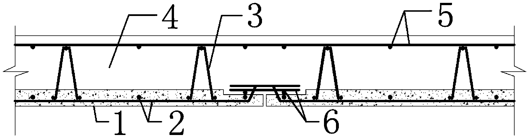
[0024] Embodiment 1: as figure 2 As shown, the laminated floor slab includes a prefabricated concrete slab 1 , a lower reinforcement mesh 2 , a truss reinforcement 3 , an additional reinforcement 6 , an upper reinforcement mesh 5 and cast-in-place concrete 4 . The truss reinforcement 3 is bound to the lower reinforcement mesh 2 and poured into the prefabricated concrete slab 1 . When splicing, add additional reinforcement 6 to the lower layer of the joint, the thickness of the two prefabricated concrete slabs 1 is reduced within the range of the additional reinforcement 6 at the joint, and the lower reinforcement near the joint can be bent at a place where there is enough thickness of the protective layer. Go over the seams. 5 frames of the upper layer of reinforcement mesh stand on the top surface of the truss reinforcement 3, and the upper layer of additional reinforcement 6 can be added to the joints, and finally the concrete is poured. It should be noted that the inner ...

Embodiment 2

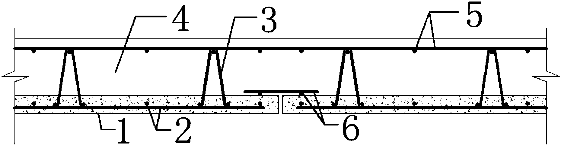
[0025] Embodiment 2: as image 3 As shown, the two precast concrete slabs 1 did not change the thickness of the precast concrete slab 1 at the joint, nor bent the lower steel mesh 2, but cut off the precast concrete slab 1, added additional steel bars 6 at the joint, and the rest Same as Example 1.


PUM

PropertyMeasurementUnit
lengthaaaaaaaaaa

Abstract

The invention discloses a jointing structure of a composite floor. The jointing structure comprises a precast concrete plate, a lower-layer steel mesh, truss steel bars, additional steel bars, an upper-layer steel mesh and cast-in-place concrete. The truss steel bars are banded on the lower-layer steel mesh poured in the precast concrete plate, the upper-layer steel mesh is erected on the top of the truss steel bars, the additional steel bars are added on the lower layer at the jointing seam of the composite floor, and the composite floor is of integrated cast-in-place concrete. By the aid of the jointing structure, rationalization of plate division and reliability of jointing structure are guaranteed, integrated performances of the structure are guaranteed, and cracks at the joint are prevented from appearing.

Description

technical field [0001] The invention relates to a division method and splicing structure of a laminated floor, belonging to the technical field of prefabricated and assembled laminated floor structures in construction engineering. Background technique [0002] With the continuous advancement of my country's construction industrialization process, the construction industry is facing new challenges, and my country's construction industry as a whole is still in an extensive development mode, which is difficult to meet the requirements for energy conservation and emission reduction proposed in the "Twelfth Five-Year Plan". After the 18th National Congress of the Communist Party of China, the building energy-saving industry has gained more opportunities for development. "Industrialization of construction and industrialization of housing" is the only way for the transformation of my country's construction industry. [0003] It is difficult to deal with the splicing joints between ...

Claims


Application Information

Patent Timeline
Patent Type & Authority Applications(China)
IPC IPC(8): E04B5/17
Inventor 叶燕华孙锐宋妍薛洲海周晓方张诗浩李炎陈浩
Owner NANJING UNIV OF TECH
Why Eureka
Try Eureka