A Method for Determining the Position of the Clamp on the Engine Pipeline

A technology of engine and engine casing, applied in the direction of machine/engine, gas turbine device, mechanical equipment, etc., can solve the problems that affect the assembly quality of the external pipeline of the engine, cannot express the installation position of the clamp, and the assembly position is uncertain, etc., to achieve Improve assembly quality, less impact, and improve the effect of final assembly

Active Publication Date: 2016-04-27
AECC SHENYANG ENGINE RES INST
View PDF5 Cites 0 Cited by
  • Summary
  • Abstract
  • Description
  • Claims
  • Application Information

AI Technical Summary

Problems solved by technology

[0003] Since the current engine general assembly drawings cannot express the precise information of the installation position of the clamps, they only indicate the relative positional relationship between the clamps and the pipeline during assembly, resulting in differences in the position of the double clamps between different engines and different assembly times of the same engine It is prone to problems such as missing clamps and uncertain assembly positions, which will affect the assembly quality of the external pipeline of the engine

Method used


Image

  • A Method for Determining the Position of the Clamp on the Engine Pipeline
  • A Method for Determining the Position of the Clamp on the Engine Pipeline

Examples


Embodiment 1

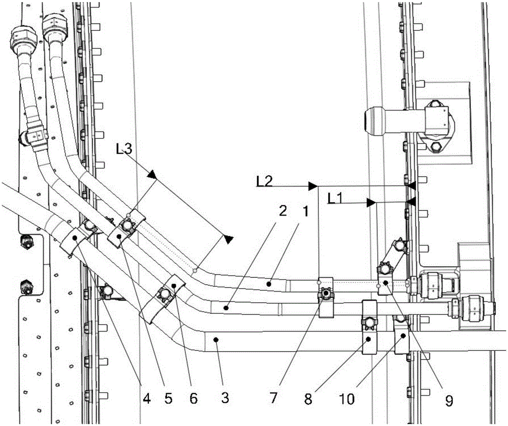
[0016] This embodiment provides a method for determining the position of the clamp on the engine pipeline, which is characterized in that: the first pipeline 1, the second pipeline 2 and the third pipeline 3 pass through the first clamp 4 and the second clamp respectively 5. The third clamp 6, the fourth clamp 7, the fifth clamp 8, the sixth clamp 9 and the seventh clamp 10 are fixed to each other or on the engine casing;

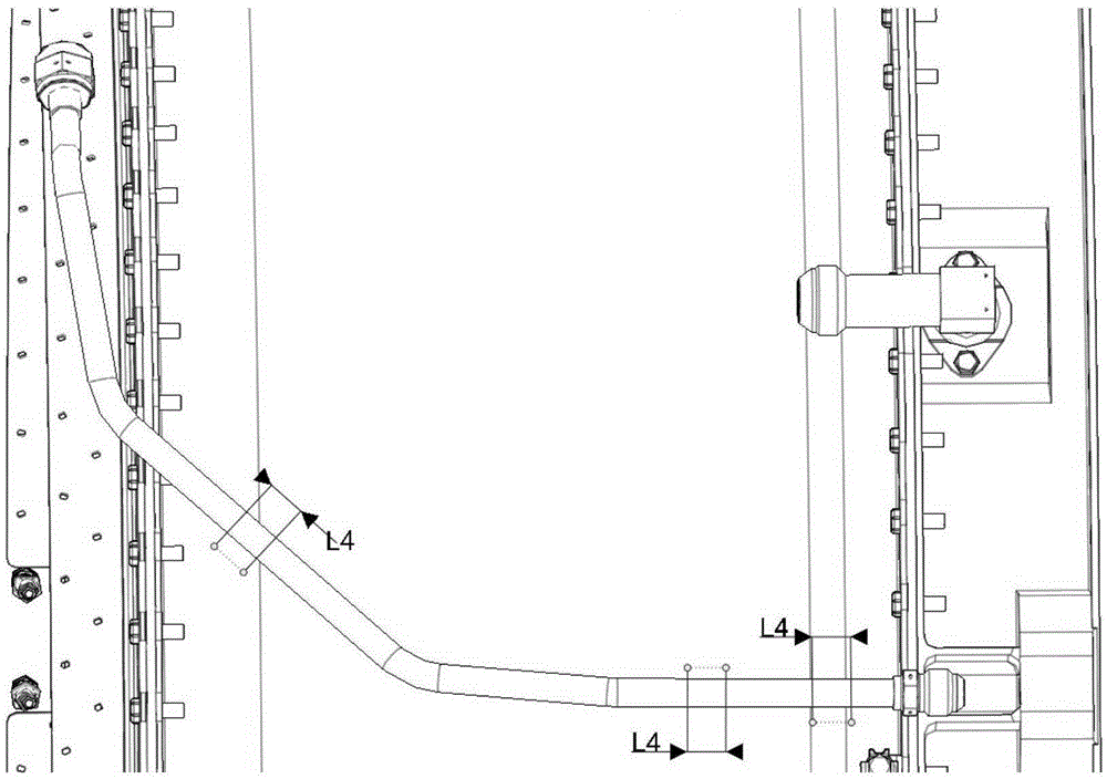
[0017] The position of the clamp on pipeline 1 is determined according to the distances L1 and L2 to the two welds and the distance L3 to the bend tangent on the pipeline; the length L4 of the clamp position is the width of the clamp.

[0018] The position of the clamp is marked by painting, sand blowing and electrolytic marking.

[0019] The width of the electrolytic paper is L4. After dipping in the electrolyte, it is wrapped on the outer wall of the pipeline, and two ring-shaped black marks are printed on the electrodes.

Embodiment 2

[0021] This embodiment provides a method for determining the position of the clamp on the engine pipeline, which is characterized in that: the first pipeline 1, the second pipeline 2 and the third pipeline 3 pass through the first clamp 4 and the second clamp respectively 5. The third clamp 6, the fourth clamp 7, the fifth clamp 8, the sixth clamp 9 and the seventh clamp 10 are fixed to each other or on the engine casing;

[0022] The position of the clamp on pipeline 1 is determined according to the distances L1 and L2 to the two welds and the distance L3 to the bend tangent on the pipeline; the length L4 of the clamp position is the width of the clamp, with a tolerance of 2mm.

[0023] The position of the clamp is marked by painting, sand blowing and electrolytic marking.

[0024] The width of the electrolytic paper is L4. After dipping in the electrolyte, it is wrapped on the outer wall of the pipeline, and two ring-shaped black marks are printed on the electrodes.


PUM


Abstract

The invention discloses a method for determining the position of hoops on engine pipelines. The method for determining the position of hoops on the engine pipelines is characterized in that a first pipeline, a second pipeline and a third pipeline are respectively fixed mutually or fixed on an engine crankcast through a first hoop, a second hoop, a third hoop, a fourth hoop, a fifth hoop, a sixth hoop and a seventh hoop; the position of hoops on the pipelines is determined according to the distances L1 and L2 from the hoops to two weld joints and the distance L3 from the hoops to a curve tangential line on the pipelines; the distance L4 of the position of the hoops is equal to the width of each hoop. The method for determining the position of hoops on engine pipelines provided by the invention has the advantages of simplicity in operation, low pipeline reliability influence, easiness for identification of marks during the using process and the like. Hoop marks are increased on the pipelines, and the hoop assembling accuracy and the final assembly and detection efficiency can be improved effectively; the assembling quality of engine external pipelines can be improved; metal felt hoops are adopted at the field to rub at the marks repeatedly, and black marks are clearly visible; the situation that the marks are rubbed and are difficult to distinguish because of the mounting and dismounting of engine pipelines is prevented.

Description

technical field [0001] The invention relates to the field of aeroengines, in particular to a method for determining the position of a hoop on an engine pipeline. Background technique [0002] Aeroengines include fuel, lubricating oil, cooling, control, starting and other systems. These systems contain a large number of pipelines and cables to supply oil, lubricate, ventilate, control and hydraulically drive the engine. Aeroengines have many external pipelines, and the installation location is limited to the limited space between the engine casing and the aircraft nacelle. At present, when laying engine pipelines, three or four pipelines are often laid side by side. Due to the limited space of the engine, a combination of single clamp and double clamp is often used for fixing, especially the number of double clamps is large. [0003] Since the current engine general assembly drawings cannot express the precise information of the installation position of the clamps, they only...

Claims


Application Information

Patent Timeline
Patent Type & Authority Patents(China)
IPC IPC(8): F02C7/20
Inventor 贾铎刘鑫周伟
Owner AECC SHENYANG ENGINE RES INST
Why Eureka
Try Eureka