Connecting structure of resonant cavity and air filter air inlet pipe

A connection structure, air filter technology, applied in combustion air/combustion-air treatment, machine/engine, engine components, etc., can solve the problems of the acoustic effect of the resonant cavity 2, the sealing of the resonant cavity 2, and the easy occurrence of distortion. , to improve the acoustic effect, good sealing, good sealing effect

Inactive Publication Date: 2013-11-27
力帆科技(集团)股份有限公司
View PDF10 Cites 1 Cited by
  • Summary
  • Abstract
  • Description
  • Claims
  • Application Information

AI Technical Summary

Problems solved by technology

Due to the angular error in the assembly between the air filter intake pipe 1 and the resonance cavity 2, distortion, deformation and obvious gaps are prone to occur at the connection position between the first connecting pipe 3 and the second connecting pipe 4, and the sponge gasket 5 is in this position, which seriously affects the sealing of the resonant cavity 2, which has a great impact on the acoustic effect of the resonant cavity 2

Method used


Image

  • Connecting structure of resonant cavity and air filter air inlet pipe
  • Connecting structure of resonant cavity and air filter air inlet pipe
  • Connecting structure of resonant cavity and air filter air inlet pipe

Examples


Embodiment Construction

[0018] The present invention will be further described below in conjunction with drawings and embodiments.

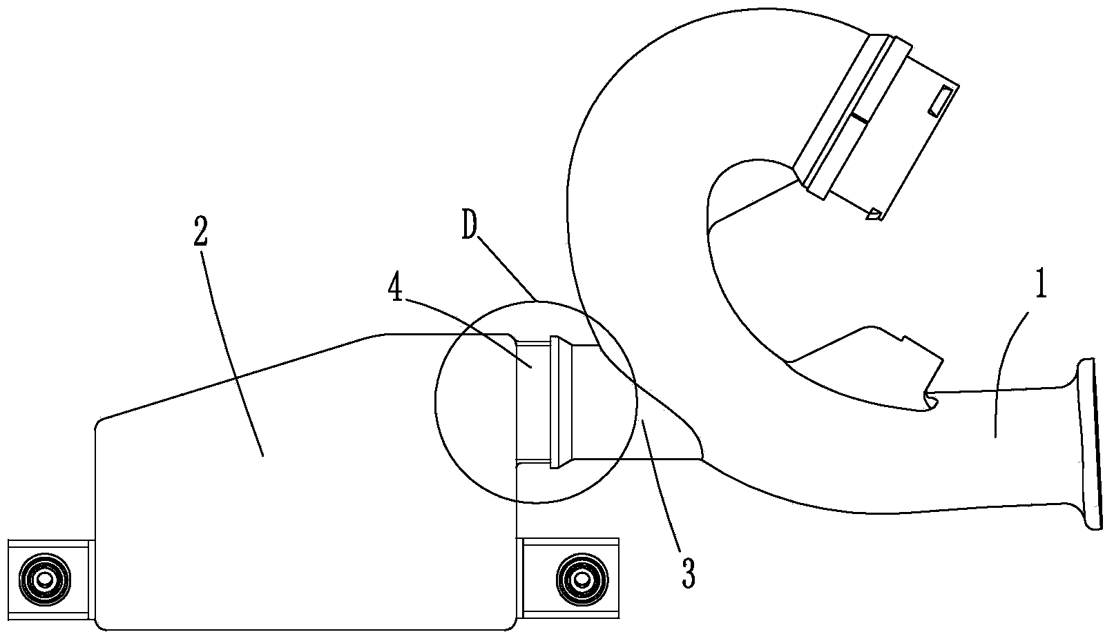
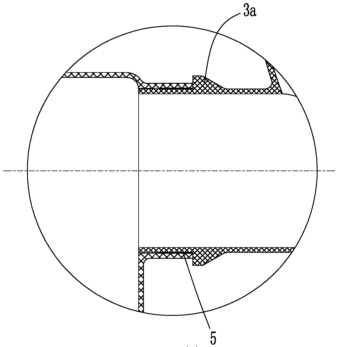
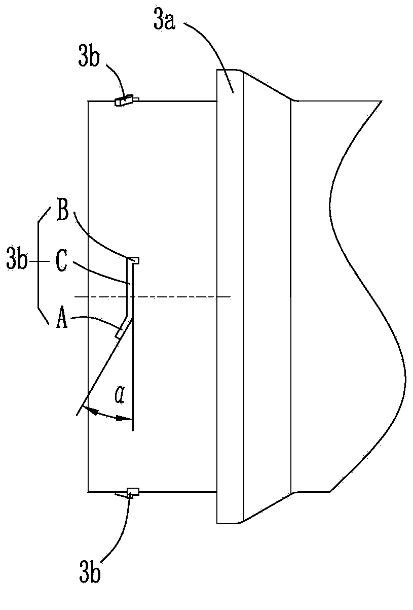
[0019] to combine figure 1 and 2 As shown, a connection structure between a resonance cavity and an air filter intake pipe is composed of an air filter intake pipe 1 , a resonance cavity 2 , a first connecting pipe 3 , a second connecting pipe 4 and a sponge gasket 5 . The air filter intake pipe 1 is provided with a first connecting pipe 3, and the resonant cavity 2 is provided with a second connecting pipe 4, and the resonant cavity 2 is connected with the first connecting pipe 3 of the air filter intake pipe 1 through the second connecting pipe 4 . The end of the second connecting pipe 4 is sleeved outside the end of the first connecting pipe 3, and an annular limit step 3a is arranged on the outer wall of the first connecting pipe 3, and the end of the second connecting pipe 4 abuts against the annular limit step 3a, the above is consistent with the structure befo...


PUM


Abstract

The invention discloses a connecting structure of a resonant cavity and an air filter air inlet pipe. The resonant cavity (2) is connected with a first connecting pipe (3) of the air filter air inlet pipe (1) through a second connecting pipe (4), an end socket of the second connecting pipe is sleeved on the outer side of an end socket of the first connecting pipe, first bosses (3b) distributed evenly along the circumference are arranged on the outer wall of the first connecting pipe, and second bosses (4a) distributed evenly along the circumference are arranged on the inner wall of the second connecting pipe. Under the guiding of guiding sections (A) of the first bosses, the second bosses rotate and move towards the air filter air inlet pipe until the second bosses are limited by a rotation stopping section (B) of the next first boss and can not keep rotating. Sponge gaskets (5) are arranged between the second bosses and annular limit steps. Assembling of the resonant cavity and the air filter air inlet pipe can reach a preset angle, conditions of distortion, deformation, obvious seams and the like at the connecting position of two components are avoided, and sealing performance of the resonant cavity is improved.

Description

technical field [0001] The invention relates to the technical field of automobile engine assembly, in particular to a connection structure between a resonance cavity and an air filter intake pipe. Background technique [0002] The air filter is an essential part of the engine intake system. The outside air must be filtered by the air filter before entering the engine intake pipe. There is usually a resonant cavity on the air filter intake pipe to reduce the intake noise through the resonant cavity. [0003] Such as figure 1 , Figure 5 As shown, the air filter intake pipe 1 is provided with a first connecting pipe 3, and the resonant cavity 2 is provided with a second connecting pipe 4. The resonant cavity 2 is first connected to the air filter intake pipe 1 through the second connecting pipe 4. The first connecting pipe 3 and the second connecting pipe 4 are in clearance fit. The position step 3a is provided with a sponge gasket 5 between the end of the second connecting...

Claims


Application Information

Patent Timeline
Patent Type & Authority Applications(China)
IPC IPC(8): F02M35/104
Inventor 陈超吴俊山吴从金
Owner 力帆科技(集团)股份有限公司
Why Eureka
Try Eureka