Lubricating oil automatic compensation device with automatic pressure relief valve
An automatic compensation and automatic draining technology, which is applied in the direction of mechanical equipment, machines/engines, liquid displacement machinery, etc., can solve problems such as frequent lubricating oil filling, inconvenient lubricating oil filling for operators, and complicated relationship between lubricating points , to achieve the effect of expanding the storage space
- Summary
- Abstract
- Description
- Claims
- Application Information
AI Technical Summary
Problems solved by technology
Method used
Image

Examples
Embodiment 1
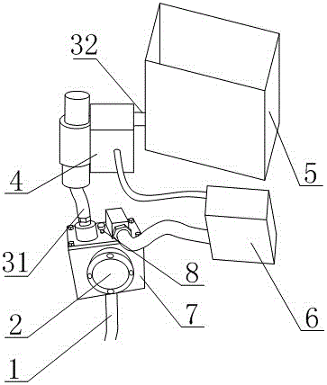
[0032] Such as figure 1 and figure 2 As shown, the lubricating oil automatic compensation device equipped with an automatic pressure relief valve includes a filling pipe 1, an oil sight glass 2, a compensation box 7, an automatic pressure relief valve 8, a first oil inlet pipe 31, a second oil inlet pipe 32, and an oil control valve 4 and the oil storage tank 5, one end of the oil filling pipe 1 is connected to the bottom of the compensation box 7, the two ends of the first oil inlet pipe 31 are respectively connected to the outlet end of the oil control valve 4 and the compensation box 7, and the two ends of the second oil inlet pipe 32 The bottom of the oil storage tank 5 and the inlet port of the oil control valve 4 are respectively fixedly connected, the automatic pressure relief valve 8 is arranged on the top of the compensation box 7, the oil sight glass 2 is arranged on the side of the compensation box 7, and the oil sight The mirror 2 is also provided with a length s...
Embodiment 2
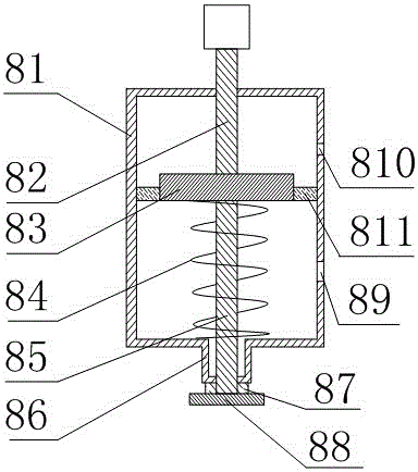
[0035] This embodiment is further improved on the basis of embodiment 1, as figure 1 and figure 2 As shown, the automatic pressure relief valve 8 includes a cylindrical valve frame 81, a disc-shaped spring stopper 83, a spring 84, a pull rod 85, a rubber pad 87, a rubber pad support block 88, a pressure relief hole 89, and Press hole 810 and elastic film 811, the two ends of described pull rod 85 are respectively fixedly connected with spring stopper 83 and rubber pad support block 88, and spring stopper 83 is positioned at valve frame body 81, and rubber pad support block 88 is positioned at valve frame body Outside the bottom end of 81, the pull rod 85 forms a clearance fit with the wall surface of the valve frame body 81, and the elastic membrane 811 is in the shape of a hollow disc. The inner wall of 81 is fixedly connected, and the spring block 83 and the elastic film 811 divide the valve frame body 811 into two parts, the upper chamber and the lower chamber, the spring...
PUM
 Abstract
Description
Claims
Application Information
 - Generate Ideas
- Intellectual Property
- Life Sciences
- Materials
- Tech Scout
- Unparalleled Data Quality
- Higher Quality Content
- 60% Fewer Hallucinations
Browse by: Latest US Patents, China's latest patents, Technical Efficacy Thesaurus, Application Domain, Technology Topic, Popular Technical Reports.
© 2025 PatSnap. All rights reserved.Legal|Privacy policy|Modern Slavery Act Transparency Statement|Sitemap|About US| Contact US: help@patsnap.com