Air flow orientating propelling system

A propulsion system and airflow technology, which is applied to the components of pumping devices for elastic fluids, non-variable-capacity pumps, pump devices, etc., can solve the problems of inability to fix the airflow direction, poor guiding performance, and low propulsion force, etc. Achieve the effect of large propulsion, strong airflow guiding performance and strong driving force

Inactive Publication Date: 2013-11-27
哈尔滨市奇正水稻种植专业合作社
View PDF4 Cites 3 Cited by
  • Summary
  • Abstract
  • Description
  • Claims
  • Application Information

AI Technical Summary

Problems solved by technology

[0008] In order to solve the problems existing in the existing airflow propulsion system, such as small propulsion force, poor guiding performance and inability to fix the airflow direction, the present invention further provides an airflow directional propulsion system

Method used


Image

  • Air flow orientating propelling system
  • Air flow orientating propelling system

Examples


specific Embodiment approach 1

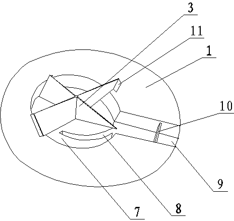
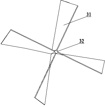
[0030] Specific implementation mode one: see figure 1 with figure 2 The airflow directional propulsion system of the present invention comprises a propeller body 1 and a blade torque propeller 3, the blade torque propeller 3 is installed above the propeller body 1, and the transmission shaft 32 of the blade torque propeller 3 is placed on the propeller body 1 is connected to the power system at the bottom, and the tail of the propeller main body 1 is provided with an airflow dredging outlet 9, and the top of the propeller main body 1 has a circular air compression chamber 7, and the blade torque propeller 3 is located in the circular air compression chamber 7, the circular air compression chamber 7 communicates with the airflow dredging exhaust port 9, the blade torque propeller 3 includes a plurality of paddle blades 31 and a transmission shaft 32, and the plurality of paddle blades 31 are annularly arrayed on the outer wall of the transmission shaft 32 above, and the conne...


PUM


Abstract

The invention discloses an air flow orientating propelling system and belongs to the technical field of power devices. The air flow orientating propelling system aims at solving the problem that the existing air flow orientating propelling system is small in propelling force and poor in guiding property and cannot fix the air flow direction. A paddle torque propeller of the air flow orientating propelling system is installed above a propeller main body, a transmission shaft of the paddle torque propeller is connected with a power system arranged at the bottom of the propeller main body, an air flow dredging vent is arranged at the tail of the propeller main body, a round air compression chamber is arranged at the top of the propeller main body, the blade torque propeller is arranged above the round air compression chamber which is communicated with the air flow dredging vent, a plurality of paddle blades are arrayed on the outer wall of the transmission shaft annularly, the connection end face of each paddle blade is in a 45-degree frontward inclining state, and the paddle blades is bent in the connection ends and transits to be in a vertical state in the tail ends. The air flow orientating propelling system supplies propelling force for mechanical systems and has large propelling force and good air flow orientation property.

Description

technical field [0001] The invention relates to an airflow propulsion system, in particular to an airflow directional propulsion system, which belongs to the technical field of power devices. Background technique [0002] The propulsion system is the core component of the mechanical system. At present, the most commonly used propulsion system is the steam turbine, and the electromagnetic propulsion system is not widely used due to the limitation of its use environment. However, the existing airflow propulsion system has not been widely used due to the following technical defects. [0003] 1. The propulsion force of the existing airflow propulsion system is small; [0004] 2. The airflow direction of the existing airflow propulsion system cannot be fixed; [0005] 3. The airflow guiding performance of the existing airflow propulsion system is poor; [0006] 4. The existing airflow propulsion system cannot be applied on the water surface. [0007] Therefore, it is urgent...

Claims


Application Information

Patent Timeline
Patent Type & Authority Applications(China)
IPC IPC(8): F04D25/08F04D29/30F01D15/02
Inventor 孙炳岐
Owner 哈尔滨市奇正水稻种植专业合作社
Why Eureka
Try Eureka