Boat propelling system

a propelling system and propeller technology, applied in the field of boat propelling systems, can solve problems such as abnormal steering of the propelling system main body

Active Publication Date: 2014-09-09
SIEMENS ENERGY INC +1
View PDF38 Cites 3 Cited by
  • Summary
  • Abstract
  • Description
  • Claims
  • Application Information

AI Technical Summary

Benefits of technology

[0007]Preferred embodiments of the present invention provide a boat propelling system that is capable of determining an abnormality regarding steering of the propelling system main body.
[0009]In a preferred embodiment of the present invention, a target pivot angle change amount is calculated by subtracting a baseline target pivot angle from a target pivot angle of the propelling system main body, and an actual pivot angle change amount is calculated by subtracting a baseline actual pivot angle from an actual pivot angle. Then, a difference between the target pivot angle change amount and the actual pivot angle change amount is obtained as a gap amount, and a comparison is made between the gap amount and the first threshold value. If the gap amount is smaller than the first threshold value, it is determined that steering of the propelling system main body is normal. On the other hand, if the gap amount is not smaller than the first threshold value, it is determined that there is an abnormality in the steering of the propelling system main body. As described, an abnormality in the steering of the propelling system main body can be determined easily by comparing the gap amount with the first threshold value.
[0011]Generally, when the hull's speed (boat speed) is slower, a behavioral change of the hull to the actual pivot angle change is smaller (in other words, the boat turns more slowly). This means that if the orientation of the hull is to be changed quickly, the user must operate the steering section quickly, which results in a quicker increase in the target pivot angle. For this reason, it can be assumed that a slower boat speed will result in a larger gap amount (steering delay) between the target pivot angle change amount and the actual pivot angle change amount even when all conditions allow appropriate steering operations. Also, in general, when the boat speed is slow, the trim angle is set to a small value in order to obtain large propulsion. Therefore, it can be assumed that a smaller trim angle will mean a slower boat speed, which will result in a larger gap amount between the target pivot angle change amount and the actual pivot angle change amount. Hence, in a preferred embodiment of the present invention, preferably, the bracket section allows the propelling system main body to pivot in an up-down direction with respect to the hull, and the boat propelling system further includes a speed information detection section arranged to detect speed information regarding a speed of the hull, a trim angle detection section arranged to detect a trim angle of the propelling system main body, and a threshold value setting section arranged to set the first threshold value based on at least one of the speed information and the trim angle. In this case, setting of the first threshold value is based on at least one of the speed information regarding the speed of the hull and the trim angle of the propelling system main body. This ensures appropriate determination of an abnormality regarding the steering of the propelling system main body in accordance with the state of travel of the hull (boat).
[0012]When the boat speed is slower, the behavioral change of the boat to the actual pivot angle change is smaller. It is desirable therefore, that a small operation of the steering section is enough to make a large change in the actual pivot angle when the boat speed is slow. In consideration of this, it is common to design a system which will narrow the steering section operation range when the boat speed is slow than when the boat speed is fast. In this case, it can be assumed that a narrower operation range means a slower boat speed and a larger gap amount between the target pivot angle change amount and the actual pivot angle change amount. Hence, preferably in a preferred embodiment of the present invention, the boat propelling system further includes an operation range setting section arranged to set an operation range of the steering section, and a threshold value setting section arranged to set the first threshold value based on the operation range. In this case, when the operation range of the steering section is small, a large first threshold value is selected based on the understanding that the boat speed is slow. This ensures appropriate determination of an abnormality regarding the steering of the propelling system main body in accordance with the state of travel of the hull.
[0014]Power supply equipment mounted in the hull varies in performance from a hull to another. Thus, an increased amount of power supply from the power supply equipment to other components than the boat propelling system can decrease power supply to the boat propelling system, which can increase the gap amount between the target pivot angle change amount and the actual pivot angle change amount. Hence, preferably in a preferred embodiment of the present invention, the actuator includes an electric motor, and the boat propelling system further includes an electric power information detection section arranged to detect electric power information regarding electric power supplied to the electric motor, and a threshold value setting section arranged to set the first threshold value based on the electric power information. In this case, when the electric power information indicates a small value, a large first threshold value is selected. This ensures appropriate determination of an abnormality regarding the steering of the propelling system main body regardless of the performance of power supply equipment mounted in the hull.

Problems solved by technology

On the other hand, if the gap amount is not smaller than the first threshold value, it is determined that there is an abnormality in the steering of the propelling system main body.

Method used


Image

  • Boat propelling system
  • Boat propelling system
  • Boat propelling system

Examples


Embodiment Construction

[0038]Hereinafter, preferred embodiments of the present invention will be described with reference to the drawings.

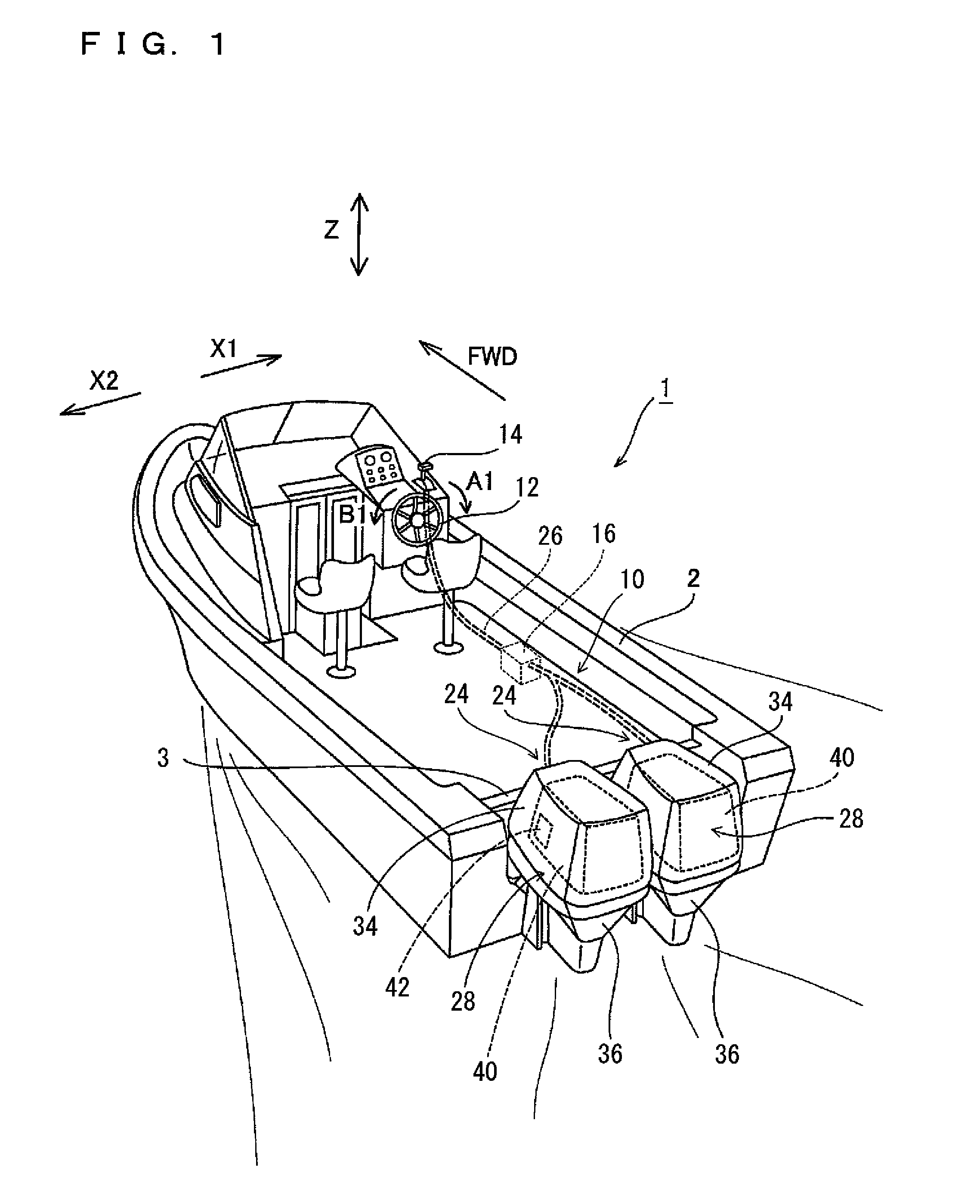
[0039]The description will cover an example in which a boat propelling system 10 according to a preferred embodiment of the present invention is installed in a boat 1. A symbol “FWD” which appears in some of the drawings indicates a forward travelling direction of the boat 1.

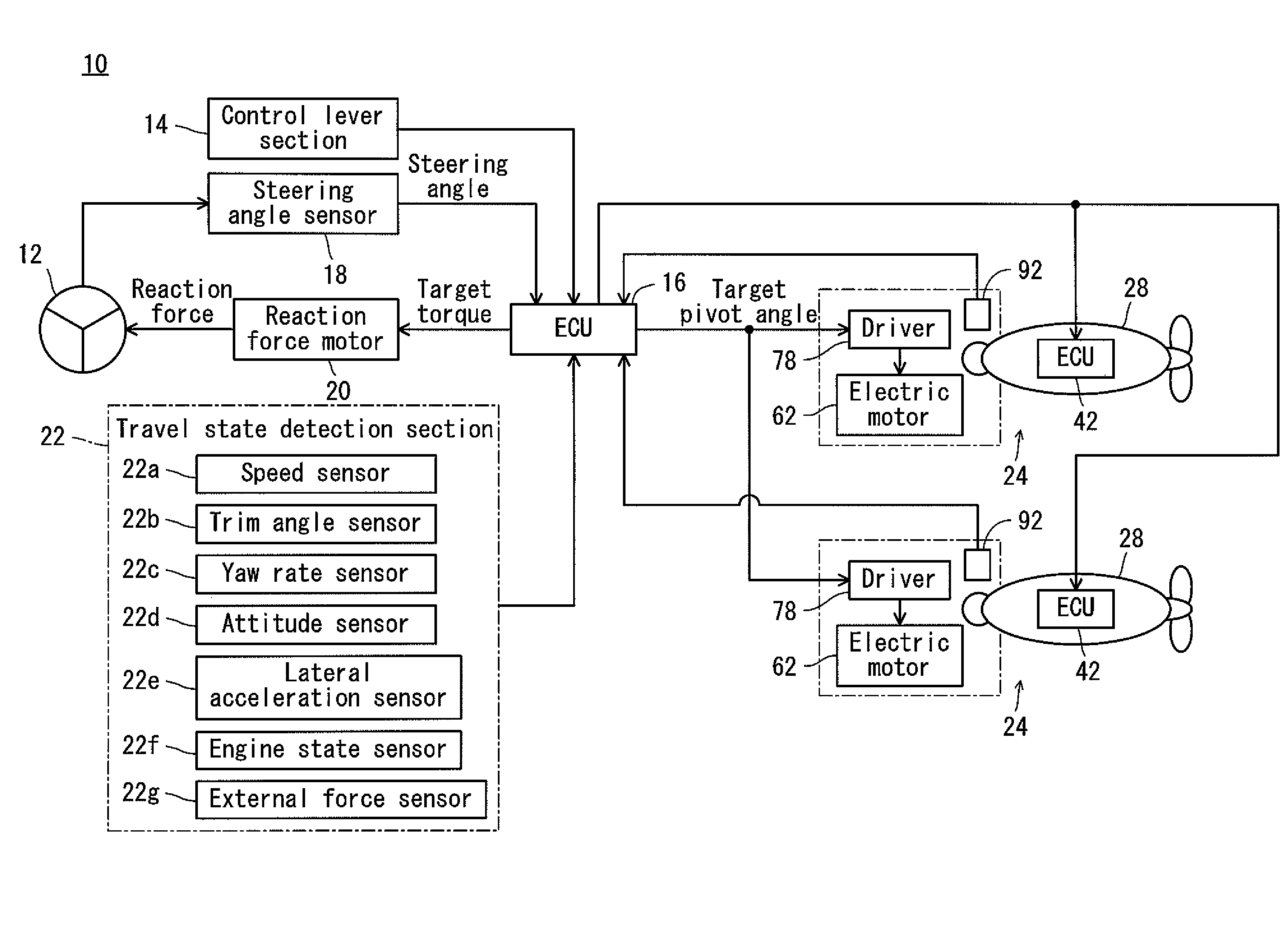
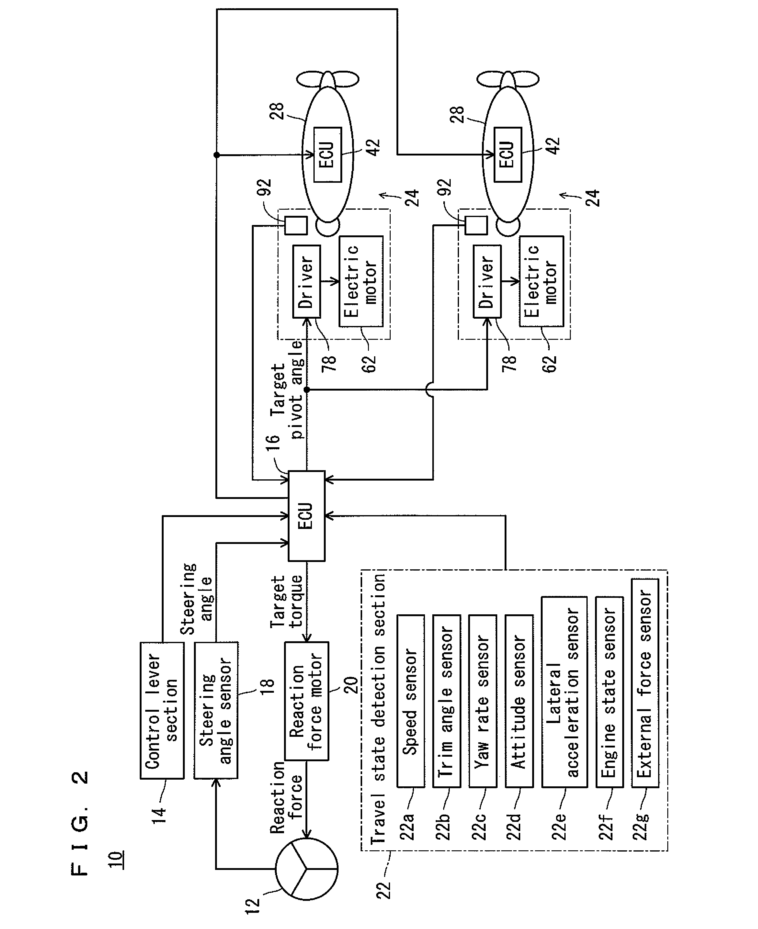
[0040]Referring also to FIG. 2, the boat 1 includes a hull 2 and a boat propelling system 10 installed on the hull 2.

[0041]The boat propelling system 10 includes a steering section 12 arranged inside the hull 2 to steer outboard engine main bodies 28 (to be described later); a control lever section 14 arranged near the steering section 12 to perform a forward-moving or rearward-moving operation of the hull 2; an ECU (Electronic Control Unit) 16 arranged and programmed to control operations of the boat propelling system 10; a steering angle sensor 18 arranged to detect a steering angle of a rotating ...


PUM


Abstract

A boat propelling system capable of determining an abnormality regarding steering of a propelling system main body includes an outboard engine main body, a steering section arranged to steer the outboard engine main body, a steering angle sensor arranged to detect a steering angle of the steering section, a pivot sensor arranged to detect an actual pivot angle of the outboard engine main body, and an ECU. The ECU calculates a target pivot angle change amount based on a target pivot angle derived from the steering angle and a baseline target pivot angle, calculates an actual pivot angle change amount based on the actual pivot angle and a baseline actual pivot angle, and obtains a gap amount between the target pivot angle change amount and the actual pivot angle change amount. Then, the ECU determines an abnormality regarding steering of the outboard engine main body based on a result of comparison between the gap amount and the first threshold value. Setting of the baseline target pivot angle and the baseline actual pivot angle is based on a result of a comparison between the gap amount and a second threshold value.

Description

BACKGROUND OF THE INVENTION[0001]1. Field of the Invention[0002]The present invention relates to boat propelling systems, and more specifically, to a boat propelling system including an electric motor arranged to pivot a propelling system main body in a right-left direction with respect to a hull.[0003]2. Description of the Related Art[0004]As disclosed in JP-A 2006-199189, for example, use of an electric motor to pivot an outboard engine (propelling system main body) in a right-left direction with respect to a hull for steering the hull is a conventional technique.[0005]According to the technique in JP-A 2006-199189, a target pivot angle of a propelling system main body (e.g., outboard engine main body) which pivots with respect to the hull, is set by using a steering wheel turning angle or the like. Then, based on an angle difference between the target pivot angle and an actual pivot angle of the outboard engine, an amount of control of the electric motor is determined. The electr...

Claims


Application Information

Patent Timeline
Patent Type & Authority Patents(United States)
IPC IPC(8): B60L3/00G05D3/00G05D1/00G06F17/00B60L15/00B63H5/125B63H20/12B63H25/00G05D1/02
CPCG05D1/0206B63H25/00B63H20/12B63H5/125
Inventor MIZUTANI, MAKOTOISHIDA, HITOSHI
Owner SIEMENS ENERGY INC
Why Eureka
Try Eureka