
Remote Measurement and Control Method and Measurement and Control System of Michelson Interference Ring

A technology of remote measurement and control and interference ring, which is applied in the field of remote measurement and control of Michelson interference ring and its measurement and control system, which can solve the problems of inconvenient experiment, vibration of interferometer, dependence of counting results, etc., so as to avoid physical operation and intuitive and clear image , the counting effect is significant

Inactive Publication Date: 2015-12-09
GUANGDONG UNIVERSITY OF FOREIGN STUDIES +7
View PDF6 Cites 0 Cited by
  • Summary
  • Abstract
  • Description
  • Claims
  • Application Information

AI Technical Summary

Problems solved by technology

But there are also the following disadvantages: this method is too strict on the placement of the device, and the thickness of the stripes will also change as the measurement progresses, and the position of the device needs to be continuously adjusted as the measurement progresses, which increases the complexity of the actual operation sex
Disadvantages: In terms of data processing, only the one-dimensional information of the interference ring is studied, and the counting results are too dependent on the collected linear area. At the same time, the two-dimensional real image of the interference ring cannot be displayed, which cannot meet the needs of the complete information research of the interference ring. The processing of linear data cannot give full play to the powerful computing functions of the microcomputer, and there is a lot of room for improvement in intelligent processing.
[0007] Whether it is the photoelectric sensor measurement method or the linear array CCD measurement method, they only focus on solving the problem of automatic counting of the interference ring. In fact, the light interference experiment is an experiment that has strict requirements on the environment. The interference of factors, such as interfering sound, causes the Michelson interferometer to vibrate slightly, causing fluctuations in the interference ring, resulting in differences in counting results
The existing experimental environment requires that the experimenters must operate in front of the experimental equipment, and they should be as careful as possible during the operation to reduce the impact on the experimental results, so that the light interferometry experiment is limited by the experimental location and time. Inconvenience

Method used


Image

  • Remote Measurement and Control Method and Measurement and Control System of Michelson Interference Ring
  • Remote Measurement and Control Method and Measurement and Control System of Michelson Interference Ring
  • Remote Measurement and Control Method and Measurement and Control System of Michelson Interference Ring

Examples


Embodiment Construction

[0048] The accompanying drawings are for illustrative purposes only, and should not be construed as limitations on this patent; in order to better illustrate this embodiment, certain components in the accompanying drawings will be omitted, enlarged or reduced, and do not represent the size of the actual product; for those skilled in the art It is understandable that some well-known structures and descriptions thereof may be omitted in the drawings. The positional relationship described in the drawings is for illustrative purposes only, and should not be construed as a limitation on this patent.

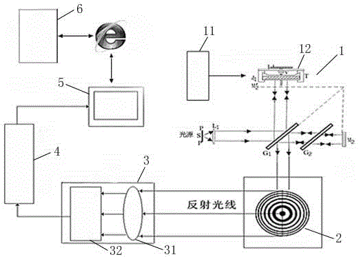
[0049] Such as figure 2 , 11 As shown, the remote measurement and control system of the Michelson interference ring includes a server-side module and a client-side module. The server-side module includes an interference fringe optical imaging module 1, an imaging screen 2, an image signal capture and conversion module 3, and a data acquisition and transmission module. 4. PC 5;

[...


PUM


Abstract

The invention relates to the technical field of Michelson interference ring measurement and control, in particular to a Michelson interference ring long-distance measurement and control method and a measurement and control system of the Michelson interference ring long-distance measurement and control method. The Michelson interference ring long-distance measurement and control method includes the steps of enabling an interference fringe optical imaging module to transmit to conduct imaging on an imaging screen, enabling an image signal capturing and conversion module to capture optical signals of images and convert the optical signals into electrical signals, using a data collection and transmission module to convert the electrical signals coming from the image signal capturing and conversion module to be converted into digital signals, transmitting collected data to a PC to conduct image processing and the counting operation, displaying results on the PC, and obtaining test data and processing the test data through a client terminal module. According to the Michelson interference ring long-distance measurement and control method and the measurement and control system, an area array CCD is adopted to collect the Michelson interference ring images, the interference ring two-dimensional image information is overall, the images are intuitive and clear, and the requirements for interference ring complete information study are met.

Description

technical field [0001] 本发明涉及迈克尔逊干涉环测控的技术领域,更具体地,涉及迈克尔逊干涉环的远程测控方法及其测控系统。 Background technique [0002] 光干涉测量技术在微电子、微光学和现代工业等领域得到广泛应用,其中最常用的技术是迈克尔逊干涉测量技术,该技术的核心是要准确地计数干涉环“冒出”或“陷入”的环数,以满足后续微距离测量的实际应用需求。 [0003] 在实际使用中干涉环的计数多采用人工法,即用人眼直接观察成像到屏幕上的干涉环,人手轻轻旋动微动手轮,每变动一个环,便人工记录一次,每次测量需数出“冒出”或“陷入”的干涉环。此方法操作简单,除了迈克尔逊干涉仪外不需要额外的测量设备,但只能适合计数小干涉环数,而实际操作时往往需要记录超过几百个以上的干涉环数,假如采用此种方法,一方面,极易造成眼睛疲劳而影响读数的准确性;另一方面测量出错后只能重新测量造成大量时间的浪费;再一方面对人眼的伤害大,非常地不人性化。 [0004] 随着近代科学技术和工业技术的迅速发展,传统的光学机械测试方法已日益不能适应近代工业和科学技术提出的高精度、高效率与自动化的测试要求。在精密测试领域中,必须注入新的活力,激光和计算机技术的出现和二者的结合为新的测试技术开辟了一条新的途径。针对人工计数的缺点,研究人员提出了关于条纹自动计数器的诸多方案,这些方案各有优点,但也存在不足。 [0005] 光电传感器测量法:工作框图如 figure 1 所示,随着光程差的变化,干涉环将交替地出现“冒出”和“陷入”,使用光电头对准迈克尔逊干涉环中心处,此时,光电头中的光敏管会随着光强信号的变化产生不同大小的光电流。 这样就将干涉环的变化转变为电信号的变化,只要对电信号进行一定的处理,就可实现对干涉环的计数。 但也存在如下缺点:该方法对器件的摆放要求过于苛刻,且随着测量的进行,条纹的厚度也将出现变化,需随着测量的进行不断地调整器件位置,增加了实际操作的复杂 sex. [0006] 线阵CCD测量法:利用线阵CCD传感器将干涉环光信号转化为电信号的图像信号捕获与转换模块,再对来自线阵CCD传感器的电信号转化为数字信号,最后将数据送至微机进行处理,在微机中实现自动计数。这样解决了光电传感器定位难和操作繁琐的缺点,同时借助微...

Claims


Application Information

Patent Timeline
Patent Type & Authority Patents(China)
IPC IPC(8): G01J9/02G05B19/418
Inventor 马文华黄煜黄晓旋黄文艳张婉柔李心广漆建军
Owner GUANGDONG UNIVERSITY OF FOREIGN STUDIES
Learn More