
Soundproof box applied to atomic force microscope

An atomic force microscope and sound insulation box technology, applied in the field of sound insulation and vibration reduction, can solve the problems of no noise reduction sound insulation equipment, rough noise decibel, not particularly strict, etc., to achieve the effect of reducing temperature, convenient and accurate experimental operation, and reducing vibration

Inactive Publication Date: 2013-11-27
LANZHOU UNIVERSITY
View PDF9 Cites 0 Cited by
  • Summary
  • Abstract
  • Description
  • Claims
  • Application Information

AI Technical Summary

Problems solved by technology

At present, traditional sound insulation facilities are made for large-scale facilities or equipment. There is no special sound insulation and vibration reduction equipment for atomic force microscope (AFM) platforms. Moreover, ordinary sound insulation equipment is relatively rough in reducing noise decibels and is not particularly strict. , it is generally believed that the influence of noise and noise can be ignored, but at the micro-nano scale, the problem of sound and vibration becomes the main factor affecting the experimental results, which can cover up subtle images and various changing signals, resulting in the failure of experimental results
It is often necessary to repeat experiments many times or start micro-nano experiments when other large-scale instruments are not in use, which brings too many changes to users. Moreover, there is currently no dedicated optical platform for scientific research at the micro-nano scale noise reduction and sound insulation equipment

Method used


Image

  • Soundproof box applied to atomic force microscope
  • Soundproof box applied to atomic force microscope
  • Soundproof box applied to atomic force microscope

Examples


Embodiment Construction

[0021] The preferred embodiments of the present invention will be described below in conjunction with the accompanying drawings. It should be understood that the preferred embodiments described here are only used to illustrate and explain the present invention, and are not intended to limit the present invention.

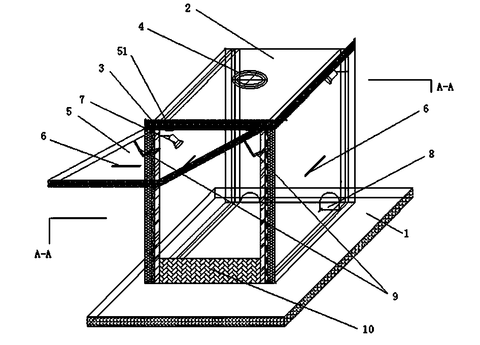
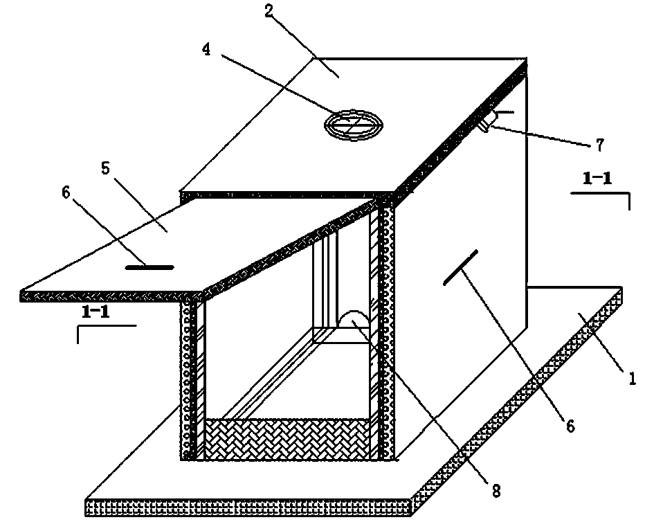
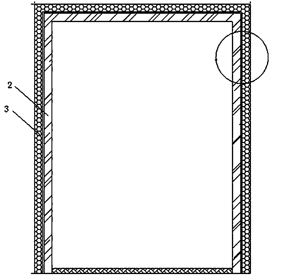
[0022] Such as figure 1 , figure 2 , image 3 , Figure 4 As shown, a soundproof box for an atomic force microscope includes a base 1 fixed on a shock-absorbing platform, an inner box 2, an outer box 3, a cooling fan 4, and a box door 5, and the inner box is sealed and docked on the base 1 2. The outer box 3 covers the outside of the inner box 2. The inner box 2 is made of vacuum-sealed double-layer plexiglass. The inner wall of the inner box 2 is pasted with sound-insulating cotton, and the surface of the sound-insulating cotton is sprayed with a sound-insulating coating. The outer box 3 includes an inner layer 31 of sound-insulating cotton and an outer layer 3...


PUM


Abstract

The invention discloses a soundproof box applied to an atomic force microscope. The soundproof box comprises a base, an inner box body, an outer box body, a cooling fan and a box door, wherein the base, the inner box body, the outer box body, the cooling fan and the box door are fixed on a damping platform, the inner box body is in sealing butt joint with the base, the outer box body covers the inner box body, the butt joint edges between the inner box body and the outer box body are sealed by rubber stripes, the cooling fan is embedded in the top of the inner box body, the box door is arranged on the front side of the inner box body, the box door is hinged to the upper portion of the inner box body, a group of hydraulic rods are respectively arranged between the two sides of the box door and the inner box body to control the box body to be opened and closed, sealing rubber stripes are arranged between the box door and the inner box body, pull handles are fixedly arranged on the box door and the two sides of the inner box body, LED lamps are arranged on the left side and the right side of the inner box body at the two opposite-angle positions, and wire output holes are reversed in the bottom of the inner box body. The soundproof box is designed at sound insulation and vibration reduction of the atomic force microscope, optical tweezers, a confocal device and other optical researching devices. The soundproof box can overcome the defects of noise, vibration and the like of the instruments in work and provide stable work environments for the instruments.

Description

technical field [0001] The invention belongs to the technical field of sound insulation and vibration reduction of nano-optical research instruments, and in particular relates to a soundproof box for an atomic force microscope. Background technique [0002] Optical platforms have been widely used in the field of scientific research, such as confocal microscopes, electron microscopes, AFM, optical tweezers and other micro-nano-level operating equipment. However, sound insulation, noise reduction and anti-static have always plagued the majority of nano-optical platform users. The sound is pervasive, and usually the noise comes from the surrounding environment, the cooling fan inside the main computer box, the cooling equipment in the controller of the large instrument itself, the air pump, the large sounding instrument in the adjacent laboratory, and the vibration of the floor itself. The static electricity is caused by the dry environment, dust, etc. entering the computer ho...

Claims


Application Information

Patent Timeline
IPC IPC(8): G01Q30/00
Inventor 张宝平王记增刘斌姚成福周又和
Owner LANZHOU UNIVERSITY
Learn More