Detection device for detecting liquid crystal module

A detection device and liquid crystal module technology, applied in the direction of nonlinear optics, instruments, optics, etc., can solve the problems of increasing product defect rate, high product defect rate, slow production speed, etc. The effect of minimizing the height of the jig and reducing the production cost

Active Publication Date: 2013-11-27
SUZHOU HUAXING YUANCHUANG TECH CO LTD
View PDF3 Cites 8 Cited by
  • Summary
  • Abstract
  • Description
  • Claims
  • Application Information

AI Technical Summary

Problems solved by technology

The existing method mainly has the following two disadvantages: 1. The detection speed is slow and the production efficiency is low; 2. The connector port on the module to be tested and the connector detection port on the detection substrate are easily damaged, which increases the product defect rate , leading to an increase in production costs
When testing, the connector on the product side is directly buckled on the connector on the contact substrate, and it needs to be completely pressed in, because the connector is relatively small, and the alignment crimping is very difficult to align, and it is easy to crush the connector. When it is opened, the connector The male end and the female end are locked with hooks, which requires force to open. It is easy to disengage the FPC pad PIN pin welded on the product, and in severe cases, the entire connector will fall off. The result of this is The production speed is slow, the product defect rate is high, and the contact substrate is damaged quickly (the life of each connector is limited to 20-50 times when fully connected), and the manufacturing cost is high

Method used


Image

  • Detection device for detecting liquid crystal module
  • Detection device for detecting liquid crystal module
  • Detection device for detecting liquid crystal module

Examples


Embodiment 1

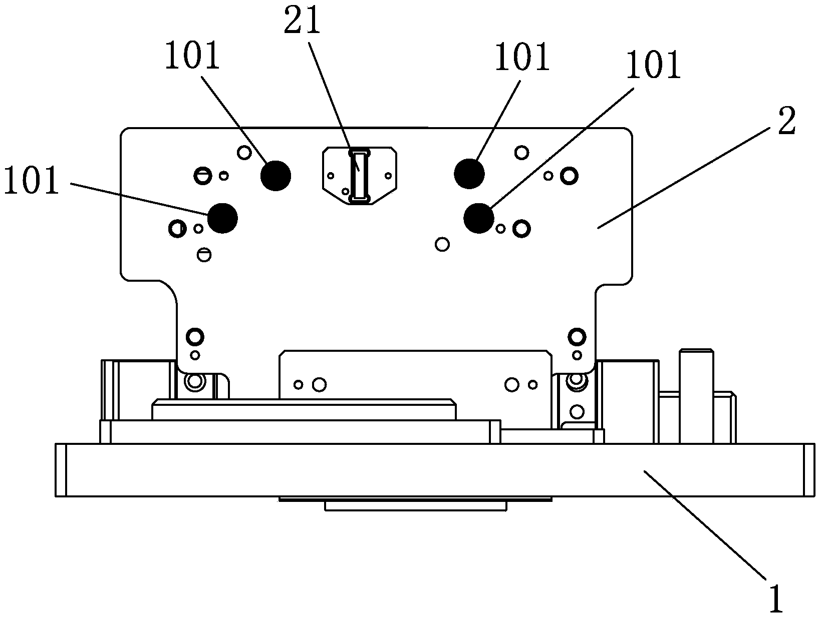
[0075] like Figures 1 to 23 As shown, a detection device for liquid crystal module detection, the detection device includes a top plate 1 and a first detection substrate 2; the first detection substrate 2 is provided with a connection for detecting the connector of the module to be tested tor detection port 21. (see figure 1 )

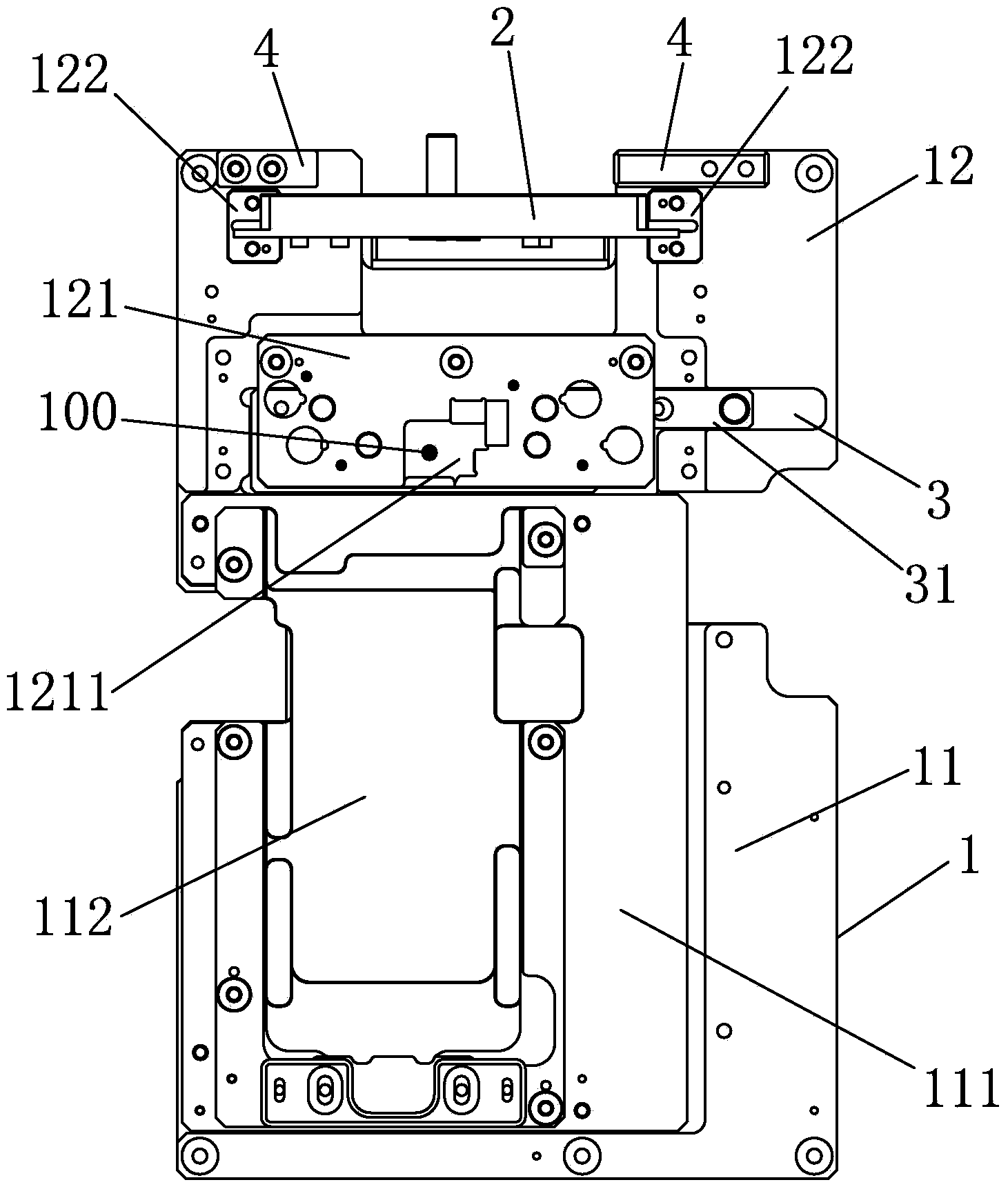
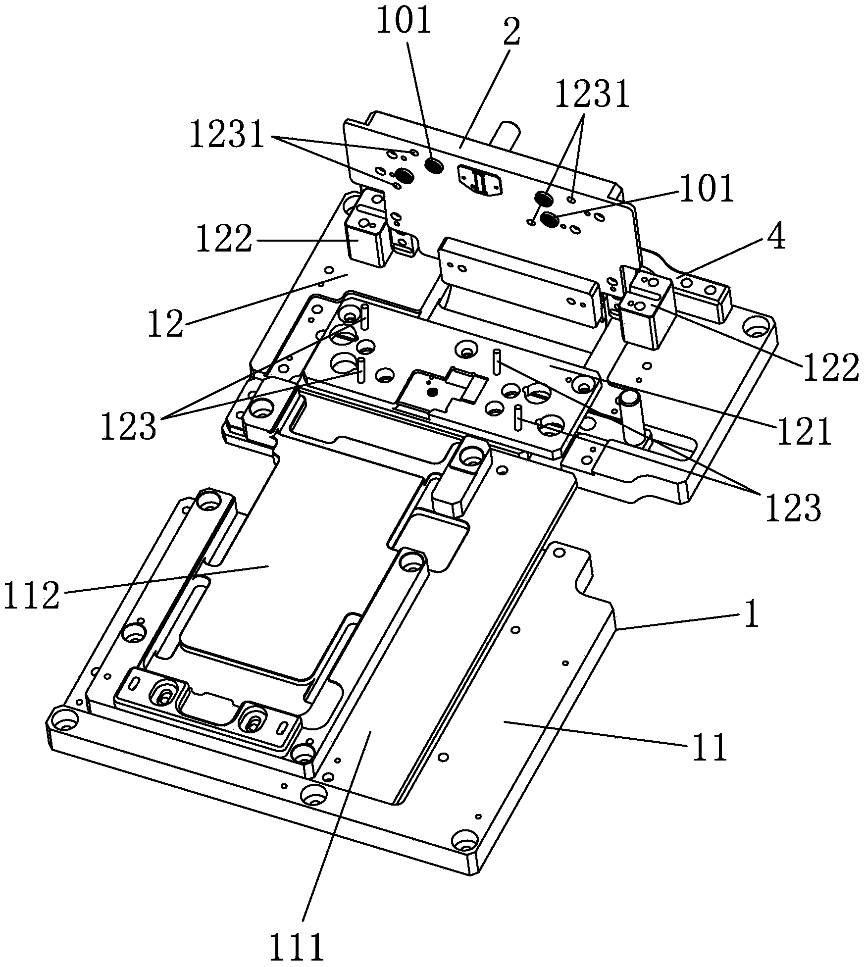
[0076] The top plate 1 includes a first top plate 11 and a second top plate 12; the first top plate 11 is sequentially provided with a backing plate 111 fixedly connected with the first top plate 11 and a backing plate 111 connected with the first top plate 11; The module supporting plate 112 to which the backing plate 111 is affixed, the module to be tested is placed on the module supporting plate 112.

[0077] The plate surface of the second second plate 12 is fixed with a limiting plate 121, which is provided with a cavity 1211 for placing the connector port of the module to be tested; the limiting plate 121 is used for positioning the module to...

Embodiment 2

[0093] The difference between this embodiment and Embodiment 1 is that: the first detection substrate is rotatably connected to the second plate through a hinge; the turned first detection substrate and the limit plate are matched and crimped together.

Embodiment 3

[0095] The difference between this embodiment and Embodiment 1 is that at least one second magnet is provided on the first detection substrate, and a metal connection part matching the position of the second magnet is provided on the surface of the limiting plate. ;

[0096] After the first detection substrate is overturned, through the cooperation of the second magnet and the metal connection part, the inner plate surface of the first detection substrate and the matching one are crimped on the plate surface of the limiting plate.

[0097] This embodiment utilizes the principle that magnets and metals attract each other. When the first detection substrate is in crimping contact with the limit plate, the second magnet and the metal connection part are attracted and docked, and the suction force makes the connector detection port on the first detection substrate Conduction with the connector port of the module under test to achieve the purpose of detection.


PUM


Abstract

The invention discloses a detection device for detecting a liquid crystal module. The detection module comprises a top plate and at least one detection base plate, wherein the top plate comprises a first top plate for holding a module to be detected and a second top plate; each detection base plate is arranged on the second top plate in a turnover manner; at least one connector detection port for detecting a connector of the module to be detected is arranged on each detection base plate. In a process of operating the detection device, the module to be detected is convenient to replace, the fault rate of a connector port in the module to be detected is reduced, the service life of the connector detection ports in the detection base plates is prolonged, the production efficiency is effectively improved, and the production cost is reduced.

Description

technical field [0001] The invention relates to a detection device, in particular to a detection device for liquid crystal module detection. Background technique [0002] Existing liquid crystal module testing fixtures are processed and assembled from black bakelite, sheet metal parts, fixtures, PCB boards, electronic components and various signal lines. It adopts a complete contact method in the detection process, that is, the connector port on the module to be tested is completely pressed into the connector detection port on the contact detection substrate. For products with multiple connector ports, the conduction detection method is also used to detect the crimping of the ports one by one. The existing method mainly has the following two disadvantages: 1. The detection speed is slow and the production efficiency is low; 2. The connector port on the module to be tested and the connector detection port on the detection substrate are easily damaged, which increases the pro...

Claims


Application Information

Patent Timeline
Patent Type & Authority Applications(China)
IPC IPC(8): G02F1/13
Inventor 陈文源曹振军应林华江斌
Owner SUZHOU HUAXING YUANCHUANG TECH CO LTD
Why Eureka
Try Eureka