Automatic-control display
A display and display technology, applied in the direction of instruments, electrical digital data processing, digital data processing components, etc., can solve problems such as cervical spine strain, achieve the effects of promoting physical health, preventing cervical spondylosis, and being easy to use
- Summary
- Abstract
- Description
- Claims
- Application Information
AI Technical Summary
Problems solved by technology
Method used
Image

Examples
Embodiment 1
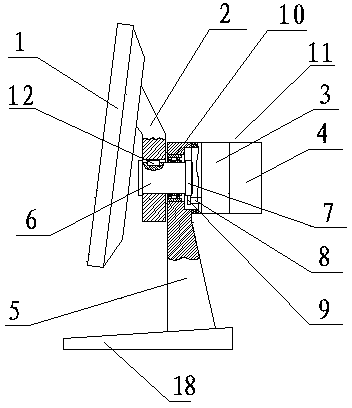
[0020] Such as figure 1 and Figure 4 As shown, an automatic control display includes a display screen 1 and a support installed on a base plate 18, and also includes a programmable logic controller (PLC) and a signal collector. The support is composed of an upper support 2 and a lower support 5 , the upper part of the lower support 5 is provided with a casing 11, and the casing 11 is provided with a stepping motor or a common motor 4 and a reducer 3 connected with the stepping motor or a common motor 4 (the transmission ratio of the reducer is 1-10000, when When the transmission ratio is 1, that is, there is no reducer), radial bearings 10 are installed in the shaft holes of the lower support 5, and the transverse rotation shaft 6 is installed in the radial bearings 10. The display screen 1 is connected with the upper support 2, and the upper support 2 is installed on the horizontal rotation shaft 6 and connected with the horizontal rotation shaft 6 through the key 12 (when ...
Embodiment 2
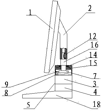
[0028] Such as figure 2As shown, a kind of automatic control display, comprises display screen 1 and the support that is installed on the base plate 18, and support is made up of upper support 2 and lower support 5, and the upper part of lower support 5 is provided with box body 15, and box body 15 is provided with a stepping motor or a common motor 4 and a reducer 3 connected with the stepping motor or a common motor 4 (the transmission ratio of the reducer is 1-10000, when the transmission ratio is 1, there is no reducer), the deceleration The device 3 has an output shaft 8, on which a gear II 9 is installed; the upper end of the box body 15 has a bearing hole, and a thrust bearing 14 is installed in the bearing hole, and a vertical rotating shaft 16 is installed in the thrust bearing 14, and the vertical rotation shaft 16 is installed in the thrust bearing 14, The lower end of the rotating shaft 16 is equipped with a gear I7, and the gear I7 is meshed with the gear II9 for...
Embodiment 3
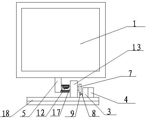
[0036] Such as figure 2 , image 3 and Figure 5 As shown, a kind of automatic control display, comprises display screen 1 and the support that is installed on the base plate 18, and support is made up of upper support 2 and lower support 5, and the upper part of lower support 5 is provided with box body 15, and box body 15 is provided with a stepping motor or a common motor 4 and a reducer 3 connected with the stepping motor or a common motor 4 (the transmission ratio of the reducer is 1-10000, when the transmission ratio is 1, there is no reducer), the deceleration The device 3 has an output shaft 8, on which a gear II 9 is installed; the upper end of the box body 15 has a bearing hole, and a thrust bearing 14 is installed in the bearing hole, and a vertical rotating shaft 16 is installed in the thrust bearing 14, and the vertical rotation shaft 16 is installed in the thrust bearing 14, The lower end of the rotating shaft 16 is equipped with a gear I7, and the gear I7 is ...
PUM
 Abstract
Description
Claims
Application Information
 - R&D
- Intellectual Property
- Life Sciences
- Materials
- Tech Scout
- Unparalleled Data Quality
- Higher Quality Content
- 60% Fewer Hallucinations
Browse by: Latest US Patents, China's latest patents, Technical Efficacy Thesaurus, Application Domain, Technology Topic, Popular Technical Reports.
© 2025 PatSnap. All rights reserved.Legal|Privacy policy|Modern Slavery Act Transparency Statement|Sitemap|About US| Contact US: help@patsnap.com