
Active optical clock generation method and device with separation of gain medium and quantum reference medium

Active Publication Date: 2016-01-20
浙江法拉第激光科技有限公司
View PDF8 Cites 0 Cited by
  • Summary
  • Abstract
  • Description
  • Claims
  • Application Information

AI Technical Summary

Problems solved by technology

In this way, two contradictory requirements are put forward for the same medium, which is difficult to be balanced on the same medium, which makes the final performance of the current active optical clock also in contradiction: if the active optical clock output with narrow linewidth is to be obtained , its power is very small, as small as picowatts or even femtowatts, which brings great difficulties to practical applications; The superior performance that should have

Method used


Image

  • Active optical clock generation method and device with separation of gain medium and quantum reference medium

Examples


Embodiment 1

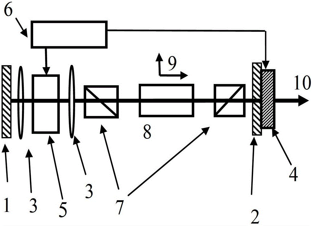
[0031] In this embodiment, an active optical clock with a typical dye gain medium and a calcium atom quantum reference medium is selected, and its structure schematic diagram is as follows figure 1As shown, it includes an optical resonant cavity, the cavity mirror 1 at the incident end is coated with a reflective film, and the cavity mirror 2 at the output end is coated with a partial reflective film, and the cavity length of the optical resonant cavity is adjusted by piezoelectric ceramics 4 . The population-inverted gain medium 5 and the quantum reference medium 8 are located in the optical resonant cavity, and the two mediums are independent of each other and separated in space. Collimating lenses 3 are arranged at both ends of the gain medium 5 . The two ends of the quantum reference medium 8 are provided with a pair of Glan-Taylor prisms 7 with orthogonal polarization directions. The gain spectrum of the gain medium 5 covers the frequencies that the quantum reference med...

Embodiment 2

[0040] This embodiment is an active optical clock device in which the semiconductor gain medium and the strontium atom quantum reference medium are separated, and its composition structure is as follows figure 1 shown. Combining the active optical clock generation process of semiconductor gain medium and strontium atomic quantum reference medium separation, the description of each component is as follows:

[0041] 1) Using a semiconductor material as the gain medium 5, first use the pump source 6 to pump the semiconductor gain medium 5 with a working wavelength of 689nm to achieve population inversion, and place it in the optical resonant cavity with the piezoelectric ceramic 4 In the optical resonant cavity formed by mirrors 1 and 2; the semiconductor gain medium 5 has a very wide gain spectrum, and covers the frequency of the 689nm transition spectrum of the quantum frequency reference medium 8 strontium atoms; the collimating lens 3 collimates the light beam .

[0042] 2)...


PUM


Abstract

The invention relates to a method and device for producing an active light clock with a gain medium and a quantum reference medium separated. The device comprises an optical resonant cavity, the quantum reference medium and the population-inversion gain medium, wherein the quantum reference medium and the population-inversion gain medium are located inside the optical resonant cavity and separated from each other in space, and the quantum reference medium is located in a magnetic field. A laser light field produces the Faraday magneto-optical rotation effect on an atomic clock transition spectral line of the quantum reference medium in the outer magnetic field, under the back feeding effect of the optical Fabry-Perot resonant cavity and under the condition that a collimating lens conducts collimation on light beams, the gain medium products stimulated radiation and reaches a laser oscillation threshold, and laser light of the active light clock is formed and output from the output end of the optical resonant cavity. According to the method and the device, the two mediums which are completely independent and separated in space are used for meeting the requirements that the output power of the active light clock is high and the narrow line of the active light clock is wide, and the output laser light has very good frequency stability and accuracy.

Description

technical field [0001] The invention belongs to the technical field of laser frequency standard and precision laser spectrum, relates to active optical clock technology, in particular to an active optical clock device in which a gain medium is separated from a quantum reference medium and a method for generating an active optical clock by using the device, which can output milliseconds The absolute laser frequency standard with watt-level power and line width much narrower than the natural line width of the quantum reference atomic spectrum is used as an atomic clock in the optical frequency band, referred to as an optical clock. Background technique [0002] The laser frequency standard, the optical clock combined with the laser frequency comb is the frequency standard with the highest precision among all precision measurement methods at present. Using the high stability and high accuracy of optical clocks, optical clocks can be used in basic scientific research to measure ...

Claims


Application Information

Patent Timeline
Patent Type & Authority Patents(China)
IPC IPC(8): H03L7/26
Inventor 陈景标庄伟
Owner 浙江法拉第激光科技有限公司
Learn More