Phase change soaking plate

A technology of vapor chamber and phase change, which is applied in the direction of cooling/ventilation/heating transformation, etc. It can solve the problems of low thermal conductivity and thick thickness, and achieve the effects of improving thermal conductivity, improving quality, and avoiding air leakage

Inactive Publication Date: 2013-11-27
SUZHOU TIANMAI THERMAL TECH
View PDF7 Cites 5 Cited by
  • Summary
  • Abstract
  • Description
  • Claims
  • Application Information

AI Technical Summary

Problems solved by technology

[0003] In order to solve the problem of thicker thickness and relatively low thermal conductivity of t

Method used


Image

  • Phase change soaking plate
  • Phase change soaking plate

Examples


Embodiment Construction

[0016] The preferred embodiments of the present invention will be described in detail below with reference to the accompanying drawings, so that the advantages and features of the present invention can be more easily understood by those skilled in the art, and the protection scope of the present invention can be more clearly defined.

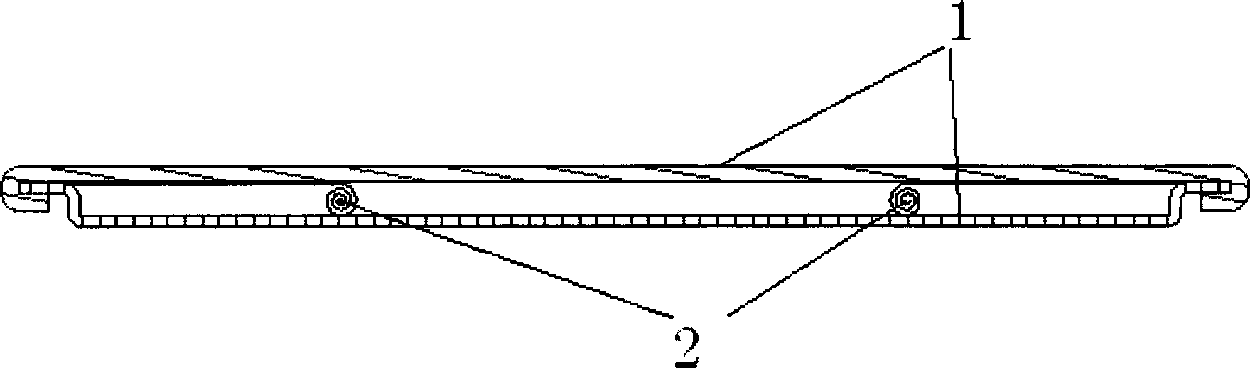
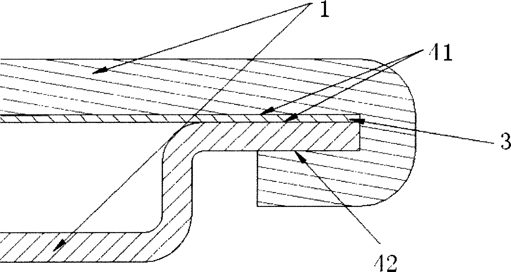
[0017] as attached figure 1 Schematic diagram of the product structure of the present invention and attachments figure 2 As shown in the schematic diagram of the welding end structure of the product of the present invention, a phase-change soaking plate includes two layers of welded metal plates 1, and between the two layers of metal plates 1 are welded a copper mesh 2 and a metal mesh plate 3. The metal mesh plate 3 There are a first welding point 41 and a second welding point 42 between the metal plate 1 .

[0018] The copper mesh 2 has a spiral multilayer structure. The metal plate 1 is a copper plate or an aluminum plate.

[0019] In the...


PUM


Abstract

The invention provides a phase change soaking plate which comprises two layers of welded metal plates, wherein a copper mesh and a metal mesh plate are welded between the two layers of metal plates, and a first welding spot and a second welding spot are arranged between the metal mesh plate and the metal plates. The copper mesh is provided with a spiral multilayer structure. The metal plates are copper plates or aluminum plates. The edge of the outer layer metal plate in the two layers of metal plates is provided with an inward bent structure, the edge of the inner layer metal plate is provided with a Z-shaped structure, and the Z-shaped structure of the inner layer metal plate is embedded into the inward bent structure of the outer layer metal plate. The phase change soaking plate has the advantages that the mesh-shaped copper plate and the spiral copper mesh are welded between the two layers of metal copper plates or aluminum plates, meanwhile a double-welding technique is adopted between the metal copper plates on two sides, therefore air leakage of a soaking material is avoided, the heat conduction coefficient of the soaking material is effectively improved, the heat conduction coefficient of the soaking material reaches 3500-5000w/mK, and the thickness is smaller than or equal to 0.5mm.

Description


Claims


Application Information

Patent Timeline
Owner SUZHOU TIANMAI THERMAL TECH
Why Eureka
Try Eureka