
Method for stamping automobile beam piece

A technology for stamping and forming of automobile beams, which is applied in the field of stamping and forming of automobile beams, can solve the problems of distortion and springback of beam shape characteristics, difficulty in correcting the mold surface, and unfavorable use of machine tools, so as to achieve small forming springback and increase material utilization. rate, the effect of reducing the number of molds

Inactive Publication Date: 2013-12-04
YESUN SHANGHAI MOLD
View PDF4 Cites 2 Cited by
  • Summary
  • Abstract
  • Description
  • Claims
  • Application Information

AI Technical Summary

Problems solved by technology

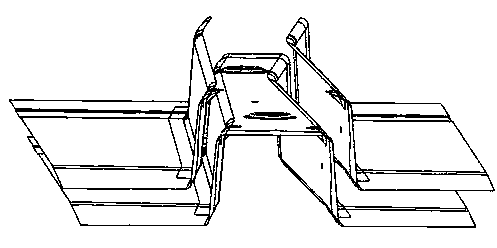
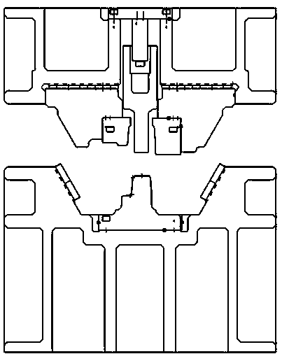
In the past, beams in auto parts mainly used drawing technology, such as figure 1 Shown is the profile of the beam workpiece; figure 2 It is a schematic diagram of the beam forming process; the material utilization rate of this process is low, and because the shape characteristics of the beam are very easy to cause distortion and springback, it is very difficult to correct the mold surface in the drawing process, and undercuts are prone to occur
The shape of beams is usually relatively simple, and the punching and trimming processes are usually relatively simple. However, the practice of making one mold for each sequence in the past is not conducive to the utilization of machine tools, especially in today's high-production machine tools where the space is tight.
Due to the above situation, the previous beam technology has gradually failed to meet the requirements of today's production, so under this requirement, an optimized guidance method is needed to reduce and solve the above contradictions and improve the competitiveness of enterprises

Method used


Image

  • Method for stamping automobile beam piece
  • Method for stamping automobile beam piece
  • Method for stamping automobile beam piece

Examples


Embodiment Construction

[0017] The invention relates to a stamping forming method of an automobile beam, which adopts a flanging process and a side shaping process to replace the previous drawing process, and reduces the relatively serious twisting and springback in the drawing process. In the flanging process, by adjusting the gap between the flanging knife block and the punch, it was found that the larger the gap between the flanging knife block and the punch, the smaller the springback of the part. In order to control the complexity of the mold and the size of the mold, it is better to have a clearance of 10-20mm between the flanging knife block and the punch. In the side shaping process, the shaping angle can also affect the springback of the part. After many experiments and researches, the shaping angle is preferably between 45° and 60°. Since the shape of the part is mainly achieved by the side shaping process, there is no need to consider the problem that the undercut of the mold surface canno...


PUM


Abstract

The invention relates to a method for stamping an automobile beam piece. A flanging process and a side rectifying process are adopted instead of the conventional drawing process; in the flanging process, a gap between a flanging cutter block and a male die is adjusted, and is 10-20 millimeters; in the side rectifying process, and the rectifying angle is 45-60 degrees. According to the method, the utilization ratio of materials is increased; a blanking die is used, so that the trimming procedure of a subsequent trimming die is reduced or the trimming die is removed; and the part quality is ensured by using the characteristics of a flange side rectifying composite die, and meanwhile the rectification of a rebounding section is facilitated. A first-order die can be reduced through flange composite side trimming, so that the die cost is saved by 10 percent; compared with direct molding, the flange side trimming composite procedure has the advantage that the defect of corrugation of parts can be reduced; and parts are shaped finally by side shaping, so that the rebounding correction of parts is facilitated.

Description

technical field [0001] The invention relates to a stamping process of an automobile beam, in particular to a method for stamping an automobile beam. Background technique [0002] With the rapid development of the domestic automobile industry, there are more and more types of automobiles, and the competition for automobiles is becoming more and more fierce. Due to the development of technology and the increase in the price of source materials, cost control in the automotive industry is extremely important. Excellent quality and effective cost control are the most important means to gain a foothold in the ever-changing automotive market. In the past, beams in auto parts mainly used drawing technology, such as figure 1 Shown is the profile of the beam workpiece; figure 2 It is a schematic diagram of the beam forming process; the material utilization rate of this process is low, and because the shape characteristics of the beam are very easy to cause distortion and springback...

Claims


Application Information

Patent Timeline
Patent Type & Authority Applications(China)
IPC IPC(8): B21D21/00
Inventor 徐海梅李军李正
Owner YESUN SHANGHAI MOLD
Learn More