Pipe clamping device

A technology for clamping devices and pipe fittings, applied in workpiece clamping devices, pipes/pipe joints/pipe fittings, pipe supports, etc., can solve the problems of poor self-locking performance, small dimensional tolerance, time-consuming and laborious loosening of workpieces, etc. Easy installation and operation, simple and compact structure, and achieve the effect of clamping force

Inactive Publication Date: 2013-12-04
QINZHOU UNIV +2
View PDF7 Cites 11 Cited by
  • Summary
  • Abstract
  • Description
  • Claims
  • Application Information

AI Technical Summary

Problems solved by technology

[0003] For example, the wedge clamping device uses the clamping force generated by the movement of the wedge to clamp the parts. It has a simple structure and is easy to operate. However, the self-locking performance of the wedge clamping device is not good, and it may fail when there is a large impact and vibration. danger; the screw clamping device adopts screw direct clamping and other components to realize the clamping mechanism of the workpiece. This clamping mechanism has the advantages of simple structure, strong versatility, unlimited stroke, reliable clamping and convenient manufacture. Tightening and loosening the workpiece takes time and effort
The eccentric clamping device is a mechanism that directly or indirectly clamps the workpiece with an eccentric member. The mechanism moves quickly, but the clamping stroke is limited by the eccentric distance, the clamping force is relatively small, and the self-locking performance is poor.
[0004] The clamping device mentioned above is generally only suitable for occasions where the dimensional tolerance of the workpiece in the clamping direction is small and the vibration is not large during processing.

Method used


Image

  • Pipe clamping device
  • Pipe clamping device
  • Pipe clamping device

Examples


Embodiment Construction

[0019] Below in conjunction with accompanying drawing, technical scheme of the present invention is described further:

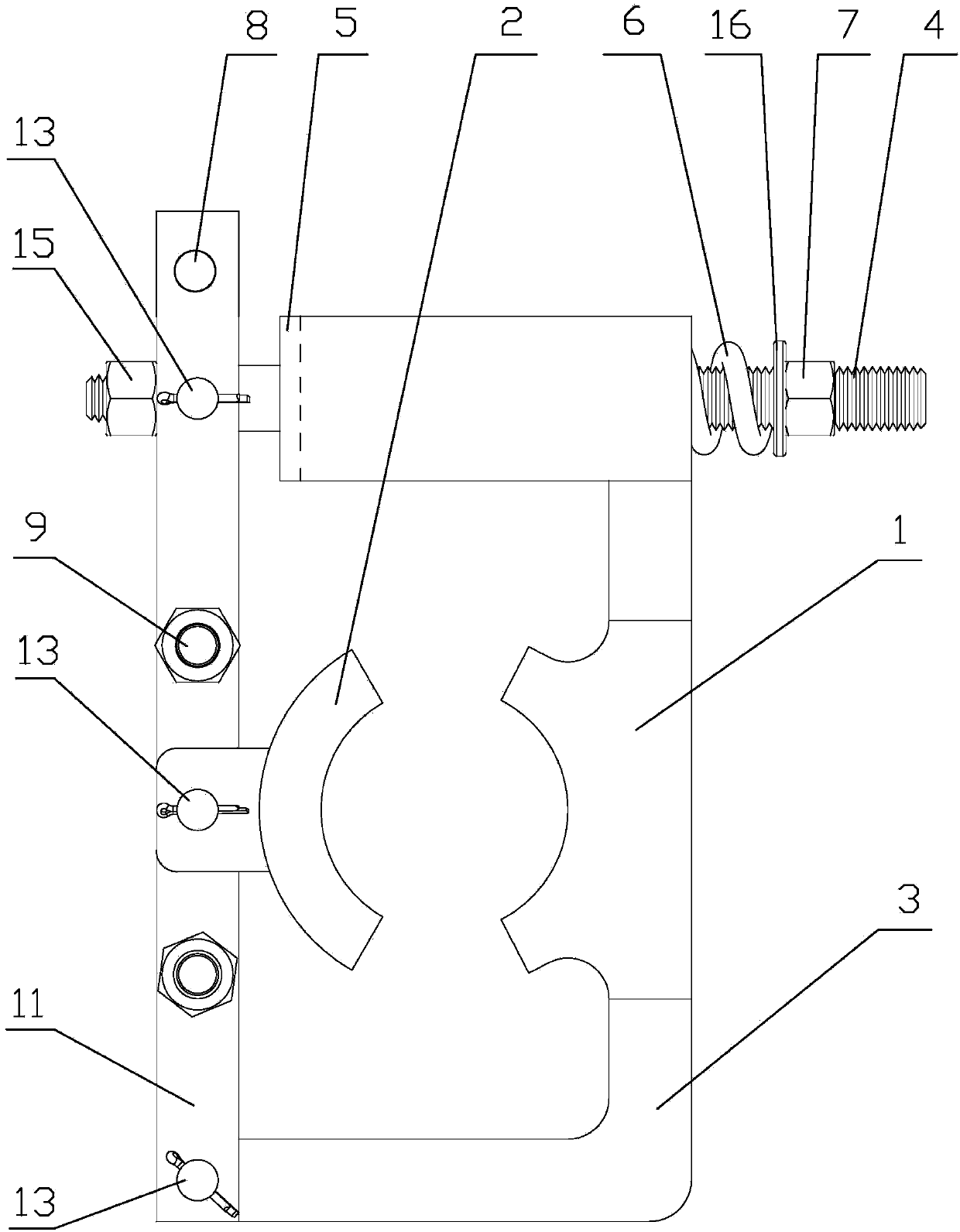
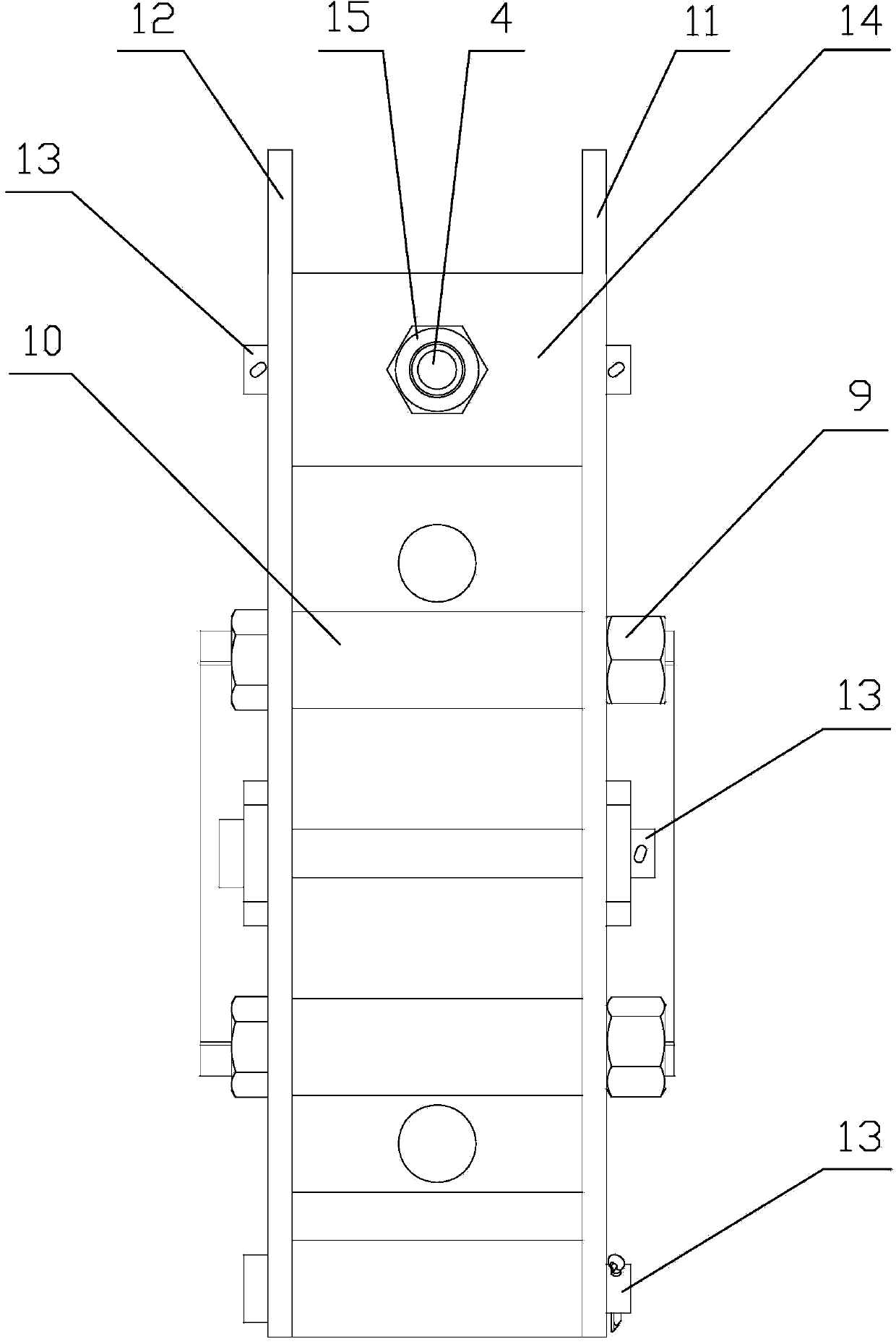
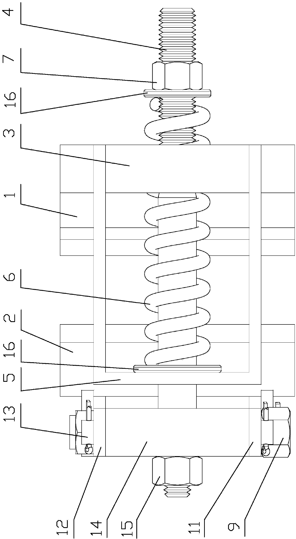
[0020] The clamping device for pipe fittings of the present invention comprises a swing arm, an "L" shaped fixed arm 3 and a clamping mechanism.

[0021] The swing arm includes an upper plate 11 and a lower plate 12 parallel to each other. The upper plate 11 and the lower plate 12 are connected as a whole with bolts 9, and the upper plate 11 and the lower plate 12 are connected by bolts 9. The axle sleeve 10 keeps the distance; the lower end of the upper plate 11 and the lower plate 12 is hinged with the transverse section end of the fixed arm 3 through the fixed pin 13, and a support block 14 is set between the upper swing end of the upper plate 11 and the lower plate 12, the described Support block 14 is hinged with upper plate 11 and lower plate 12 by fixed pin 13; In the tight clamping state, the upper plate 11 and the lower plate 12 are parallel to the...


PUM


Abstract

The invention discloses a pipe clamping device. The pipe clamping device comprises a fixed clamping block, a movable clamping block, a swinging arm and a folding fixed arm, wherein the fixed clamping block and the movable clamping block are used for clamping a pipe; one end of the swinging arm is hinged to one end of the fixed arm; the other swinging end of the swinging arm is connected with the other end of the fixed arm through a clamping mechanism in a locking way; the fixed clamping block is fixedly connected to the fixed arm; the movable clamping block is hinged to the swinging arm; the clamping mechanism comprises a screw, a spring baffle and a spring; the spring baffle is fixedly connected to the fixed arm; one end of the screw is positioned on the swinging arm; a body of the screw penetrates through the spring baffle and is sleeved with the spring; an adjusting nut is screwed at the other end of the screw and is used for extruding the spring on the spring baffle so as to tightly pull the swinging arm toward the fixed arm; pin holes are formed in one swinging end of the swinging arm and are reserved installation holes of an unlocking mechanism which is used for pushing the swinging arm away from the fixed arm. The pipe clamping device has the integrated advantages of a screw clamping mechanism and a lever mechanism, and is simple and compact in structure and convenient to install and operate.

Description

(1) Technical field: [0001] The invention relates to the field of mechanical equipment clamping, in particular to a pipe fitting clamping device which can provide clamping force by a mechanical mechanism or a hydraulic mechanism. (2) Background technology: [0002] Clamping devices are used in many fields, and clamping devices with different clamping shapes are used for different purposes. Analyzing the clamping schemes in various fields, the parts that play a basic clamping role in the clamping device include wedges, spirals, eccentrics, levers, etc., and the clamping device composed of them. [0003] For example, the wedge clamping device uses the clamping force generated by the movement of the wedge to clamp the parts. It has a simple structure and is easy to operate, but the self-locking performance of the wedge clamping device is not good, and it may fail when there is a large impact and vibration. danger; the screw clamping device adopts screw direct clamping and othe...

Claims


Application Information

Patent Timeline
Patent Type & Authority Applications(China)
IPC IPC(8): B25B11/00F16L3/10
Inventor 李尚平薛斌麻芳兰陈远玲沈中华周敬辉陆安山高建立黄国弟罗延杨正海
Owner QINZHOU UNIV
Why Eureka
Try Eureka