
Self-rearranging mortise and tenon joint

A self-resetting and mortise-and-mortise technology, which is applied to the reinforcement of beam-column mortise-and-tenon joints in new wooden structures, mortise-and-mortise joints, and beam-column mortise-and-tenon joints, can solve the problems of difficult restoration, difficult replacement and maintenance, and high repair costs. Significance and economic benefits, reduced maintenance and repair costs, and the effect of avoiding overhaul

Inactive Publication Date: 2013-12-04
NANJING UNIV OF TECH
View PDF7 Cites 10 Cited by
  • Summary
  • Abstract
  • Description
  • Claims
  • Application Information

AI Technical Summary

Problems solved by technology

[0005] 1) Not easy to replace and overhaul
For iron reinforced components, it is difficult to replace them due to corrosion problems, and at the same time brings potential safety hazards; for FRP reinforcement methods, since FRP is pasted on the surface of wooden components with structural adhesive, it is difficult to replace, and it is not easy to repair the reinforced parts. overhaul
[0006] 2) The problem of difficult reset after the earthquake still exists
Traditional reinforcement methods can generally improve the stiffness of mortise and tenon joints, and at the same time have a certain energy dissipation capacity, but after the earthquake, there are still residual deformations, and it is still difficult to restore the position, and the repair cost is also high

Method used


Image

  • Self-rearranging mortise and tenon joint
  • Self-rearranging mortise and tenon joint
  • Self-rearranging mortise and tenon joint

Examples


Embodiment 1

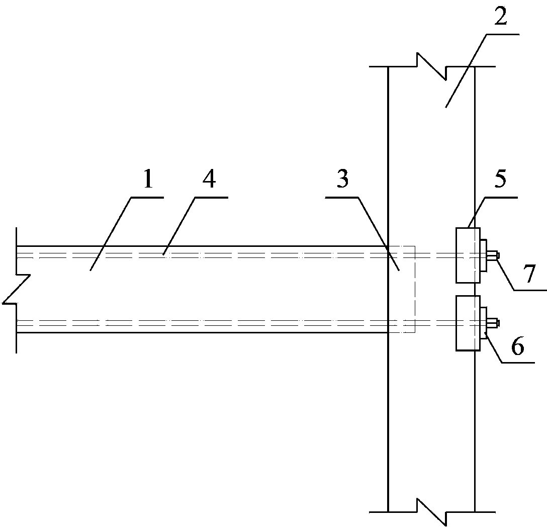
[0029] like figure 1 , 2 Shown in and 3, a kind of self-resetting tenon and mortise joint, including wooden beam 1, wooden column 2, tenon and tenon joint 3 and prestressed tendon 4 between the beam and column, between the wooden beam 1 and the wooden column 2, through the tenon and tenon joint The node 3 is connected, the prestressed tendon 4 runs through the wooden beam 1 and the wooden column 2 along the longitudinal direction of the wooden beam, and the end of the prestressed tendon 1 passes through the anchor plate 5, the anchor pad 6 and the anchor 7, and is on the back of the wooden column 2. Fix it to one side of the wooden beam 1.

[0030] The cross section of the wooden beam 1 is rectangular, and the cross section of the wooden column 2 is circular.

[0031] The material of the wooden beam 1 is one of logs, sawn timber, glulam (glulam), laminated veneer lumber (LVL), parallel-slice glulam (PSL), laminated wood-slice glulam (LSL), and other engineered woods . The ...

Embodiment 2

[0036] like Image 6 As shown in the figure, a self-resetting mortise and tenon joint, the rest of the structure is the same as that of Embodiment 1, the difference is that the cross section of the wooden column 2 is square.

Embodiment 3

[0038] like Figure 7 and 8 As shown, a self-resetting mortise and tenon joint, the rest of the structure is the same as that of Embodiment 1, the difference is that: the tenon and mortise joint 3 is a through tenon.


PUM


Abstract

The invention discloses a self-rearranging mortise and tenon joint which comprises a wooden beam, a wooden column, a mortise and tenon joint body between the beam and the column and a prestress rib. The wooden beam and the wooden column are connected through the mortise and tenon joint body. The prestress rib penetrates through the wooden beam and the wooden column in the longitudinal direction of the wooden beam. The end portion of the prestress rib is fixed on one side, with the back toward the wooden beam, of the wooden column through an anchor plate, an anchor pad plate and an anchor. The self-rearranging mortise and tenon joint has the ideal advantages that strong bending-resistant capacity and energy-consuming-resistant capacity are achieved, the joint can guarantee structure stability under low quake, structure deforms greatly and structure damage is controlled under high quake, and structure self-rearranging effect is achieved after quake.

Description

technical field [0001] The invention belongs to the field of civil engineering, relates to a mortise and tenon joint, in particular to a beam-column mortise-and-mortise joint of a wooden structure of an ancient building, which is mainly (but not exclusively) used for the reinforcement of beam-column mortise-and-mortise joints of existing wooden structures and after earthquake damage. Repair can also be used for the reinforcement of new wooden beam-column tenon-mortise joints. Background technique [0002] Wooden structures in my country have a long history. From ancient palace buildings, temples and halls to residential buildings, a large number of ancient wooden structures are used. At the same time, the ancient wooden structures are widely distributed, almost all over the country. The famous ancient wooden structures that have been passed down to the present are: Beijing Forbidden City, Shanxi Yingxian Wooden Pagoda, Jixian Dule Temple, Chengde Mountain Resort, etc. The wo...

Claims


Application Information

Patent Timeline
IPC IPC(8): E04G23/02E04B1/58E04B1/48E04C5/12
Inventor 杨会峰陆伟东刘伟庆鞠冬冬岳孔
Owner NANJING UNIV OF TECH
Learn More