
Longwall mining machine and a linepan section

A mining machine and longwall technology, applied to conveyors, cutting machinery, slitting machinery, etc., can solve problems such as production delays, poor loading characteristics of the middle slot, and inability to load cut materials

Active Publication Date: 2013-12-04
JOY GLOBAL UNDERGROUND MINING LLC
View PDF8 Cites 5 Cited by
  • Summary
  • Abstract
  • Description
  • Claims
  • Application Information

AI Technical Summary

Problems solved by technology

This AFC mid-chute advance can arise from the following reasons: poor loading characteristics of the mid-chuck; and the inability of the shearer to be loaded through the small hole available between the underside of the shearer arm and the top of the AFC mid-chute. cutting material
The compaction of the material being cut also causes problems with the horizontal control of the AFC groove line as a whole (vertical steering problem), which can delay production

Method used


Image

  • Longwall mining machine and a linepan section
  • Longwall mining machine and a linepan section
  • Longwall mining machine and a linepan section

Examples


Embodiment Construction

[0020] Before describing in detail any individual embodiments of the invention, it is to be understood that the invention is not limited in application to the details of construction and the arrangement of components set forth in the following description and shown in the drawings below. The invention is capable of other independent embodiments and of being practiced or carried out in various ways.

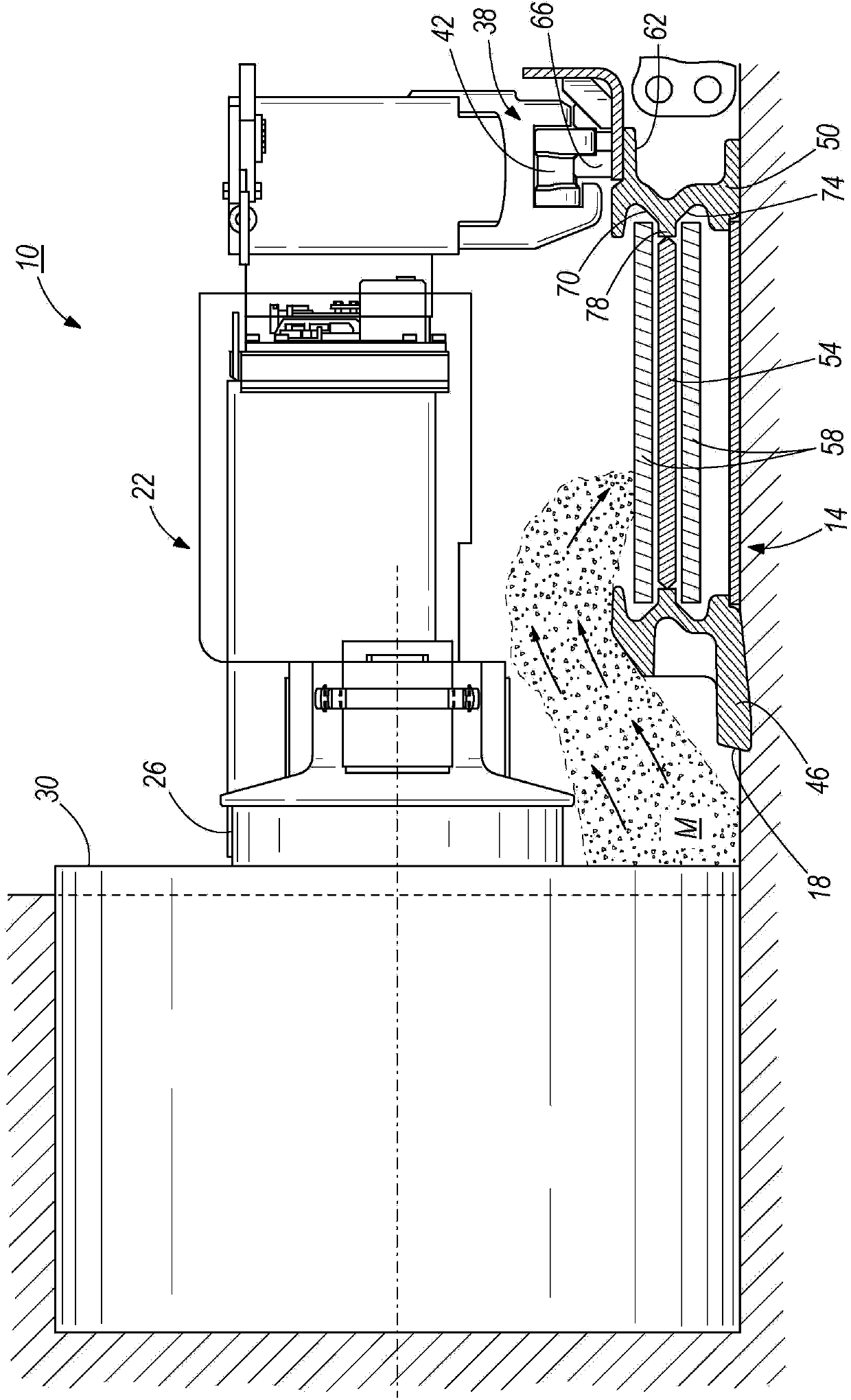
[0021] figure 1 A longwall mining machine 10 is shown comprising an Armored Conveyor (AFC) 14 having a plurality of central trough sections 18 (one shown), and a coal mining drum Machine 22. The drum shearer 22 includes: a cutting drum 26 for cutting material M (eg, coal) from a mining face 30; and a shoe 34 (see Figure 7 ), the shoe 34 straddles the AFC 14 to support the shearer 22 . Such as figure 1 As shown in , traction assembly 38 includes drive sprocket 42 for pulling drum shearer 22 along mining face 30 .

[0022] Each mid-trough section 18 of the AFC 14 includes a fa...


PUM


Abstract

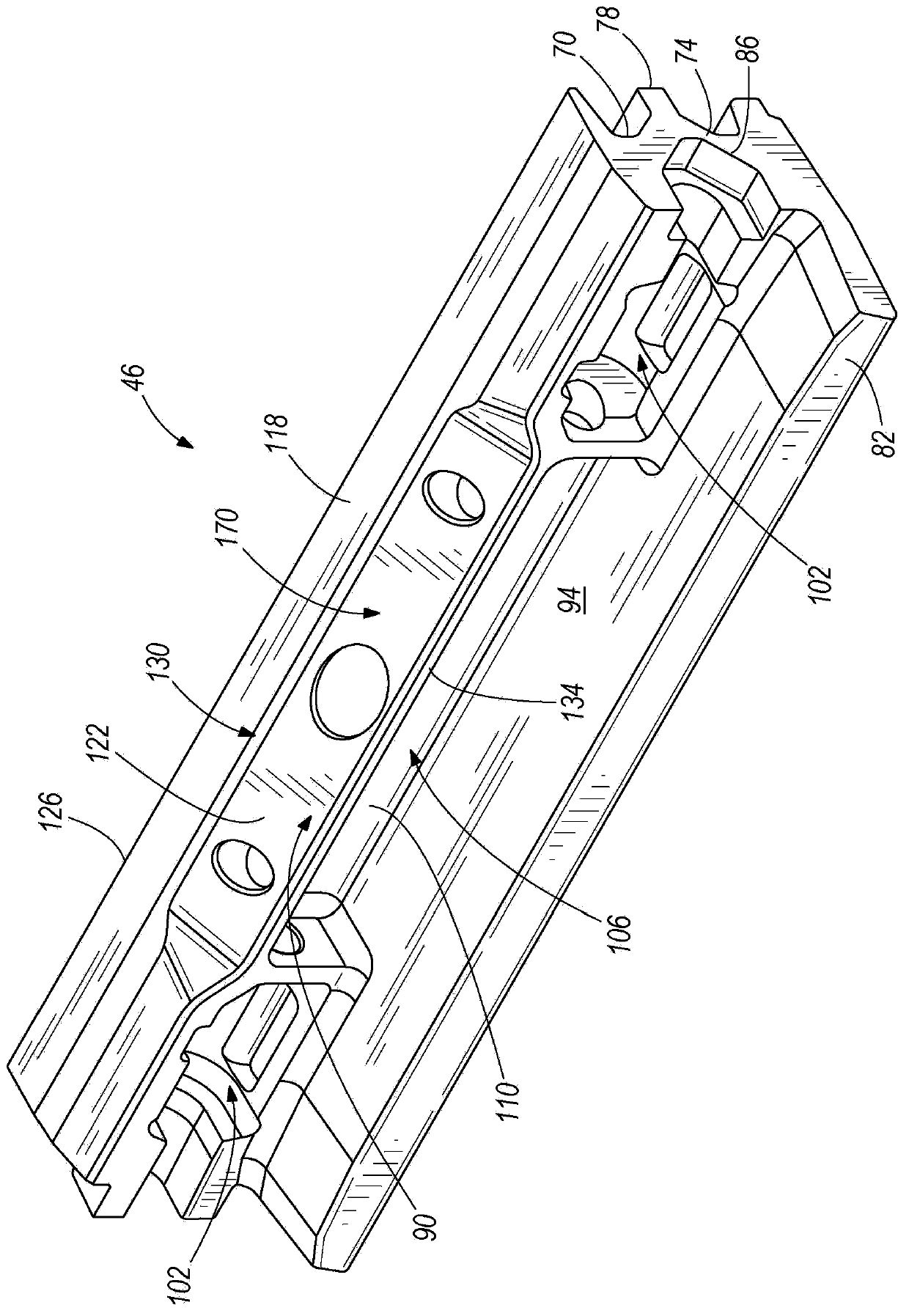
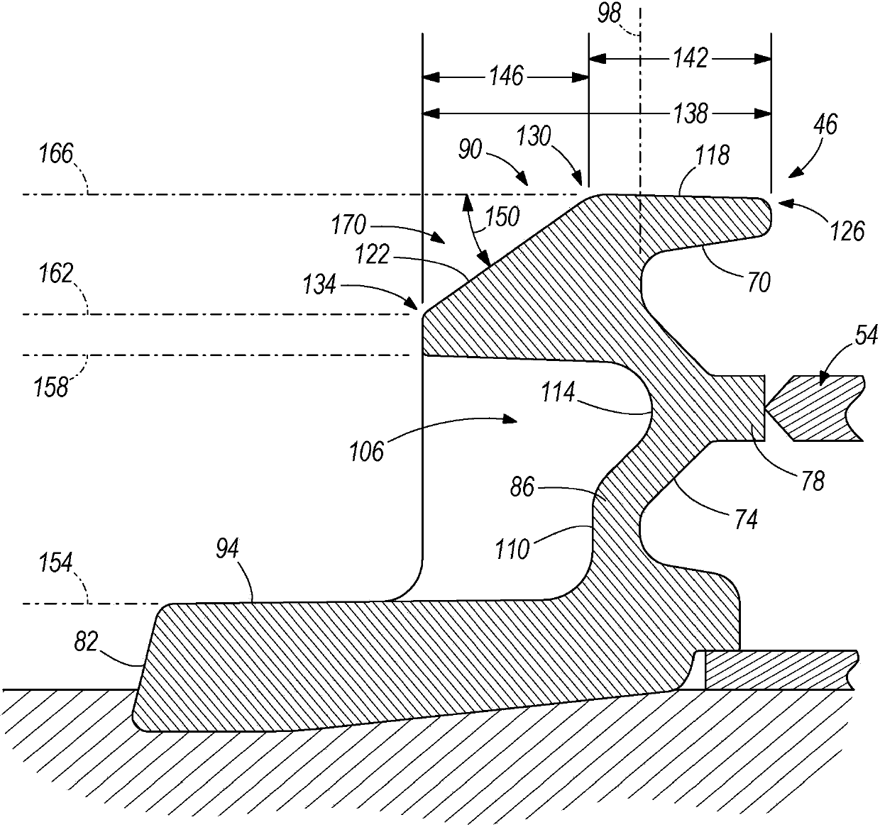
This invention discloses a longwall mining machine and a linepan section. The linepan section may include a face-side rail, a gob-side rail opposite the face-side rail, and a conveyor pan between the face-side rail and the gob-side rail. The face-side rail may have a generally horizontal top surface at a top surface height and with a top surface width, an angled loading surface extending toward the mining face and the ground surface and arranged at an oblique angle relative to the top surface, the loading surface being at a loading height and with a loading surface width, the loading surface width being at least about 25 percent of the total width, and a material cavity defined in the face surface below the loading surface and recessed toward a gob-side.

Description

technical field [0001] The present invention relates generally to a longwall mining machine and in particular to a linepan for an armored conveyor. Background technique [0002] In a longwall miner, the shearer traverses along the pan line of an Armored Face Conveyor (AFC) to access material from the face. The AFC consists of several mid-chute segments joined together to form a conveyor for moving cut material away from the work face. An exemplary AFC including a mid-tank section or conveyor tank is disclosed in US Patent 7,896,444, filed March 1, 2011, the entire contents of which are incorporated herein by reference. [0003] AFC mid-chute for low and medium seam applications can be prevented from advancing by compaction of the cut material between the face side of the mid-chute and the cutting face of the material being cut. This AFC mid-chute advance can arise from the following reasons: poor loading characteristics of the mid-chuck; and the inability of the shearer to...

Claims


Application Information

Patent Timeline
IPC IPC(8): E21C25/06E21C27/20
CPCE21C25/06B65G19/28E21C27/20E21C35/20E21C35/12
Inventor 罗恩·维西阿德里安·琼斯
Owner JOY GLOBAL UNDERGROUND MINING LLC
Learn More